04 / ENGINEERING GUIDE
Key Dimensions & Interface Requirements
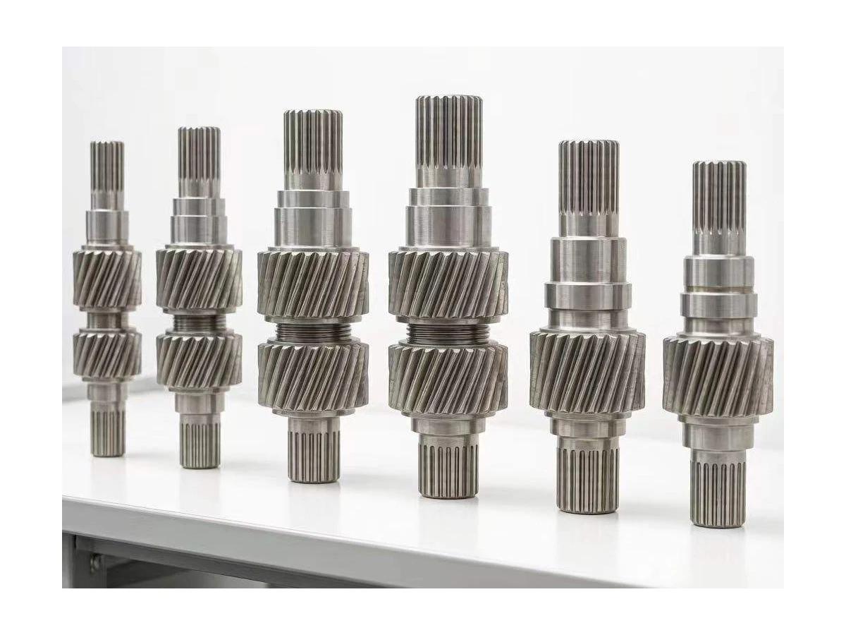
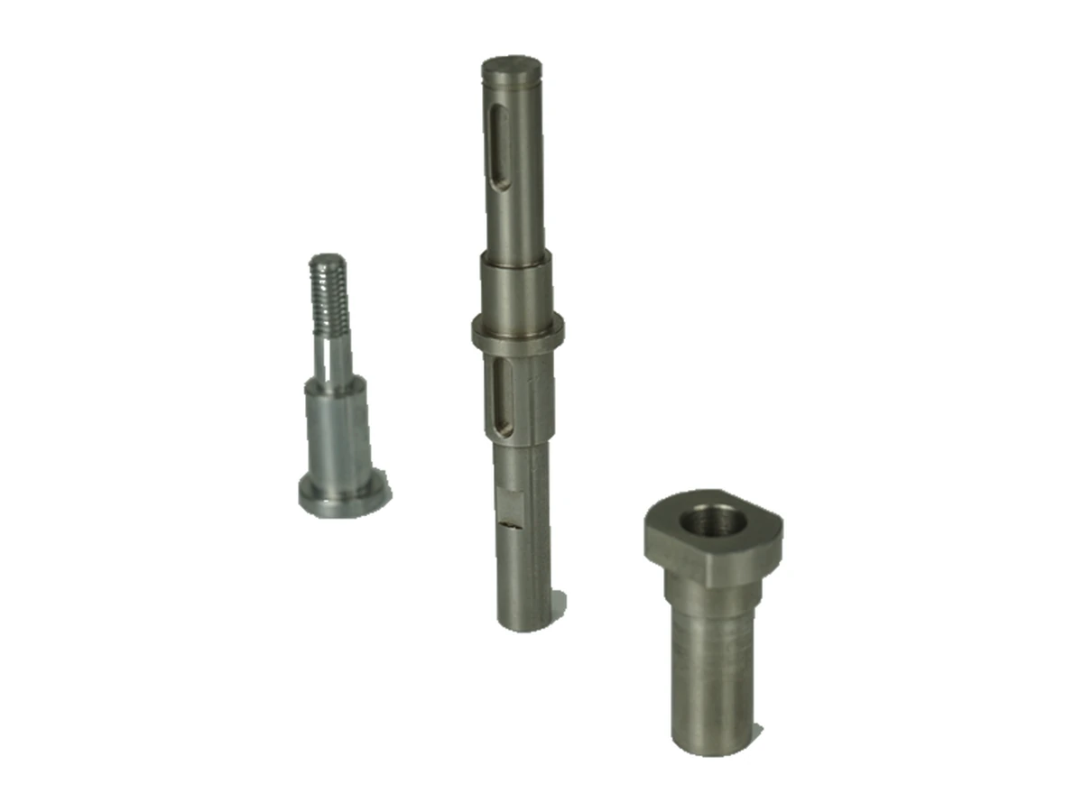
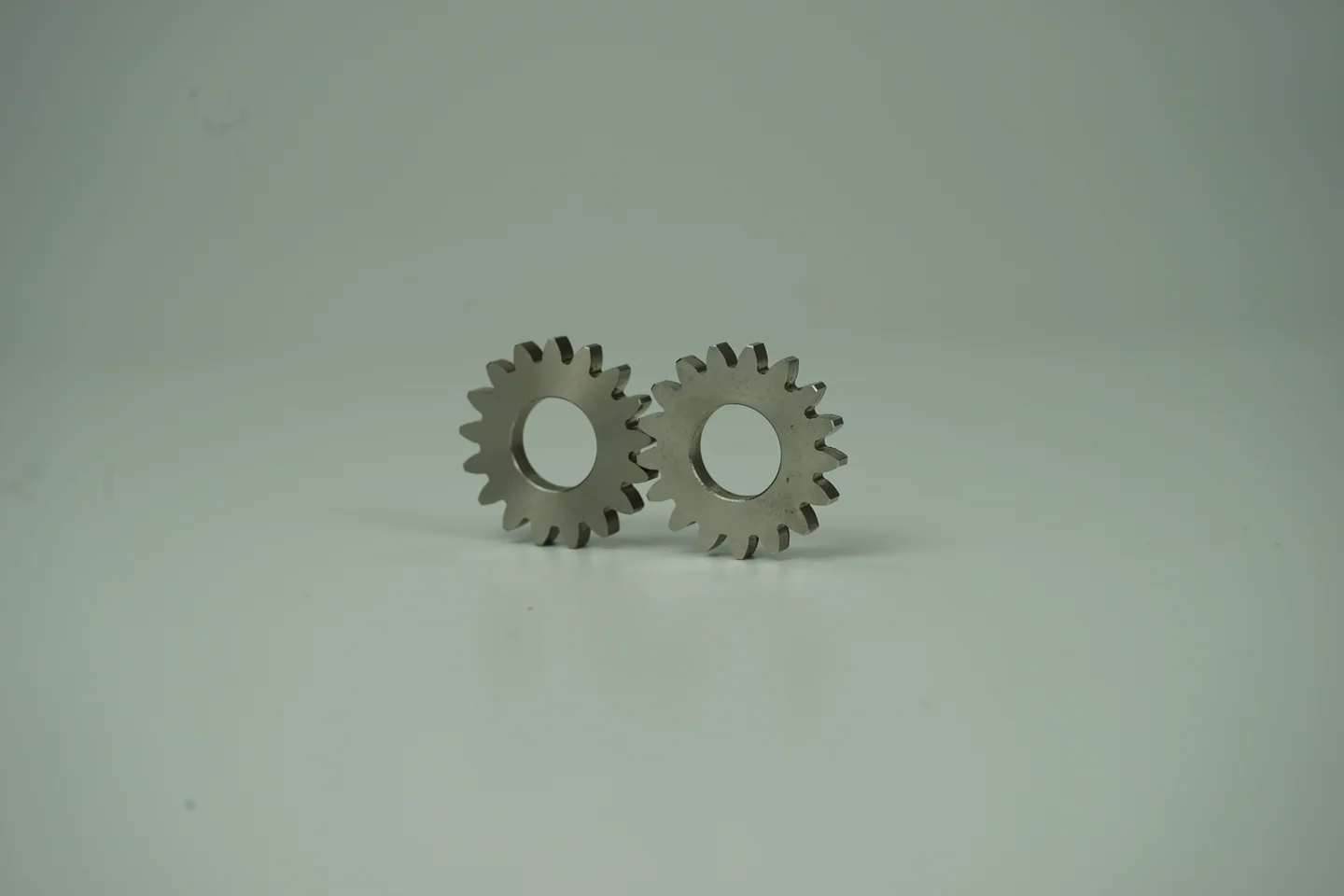
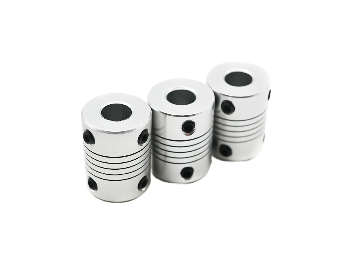
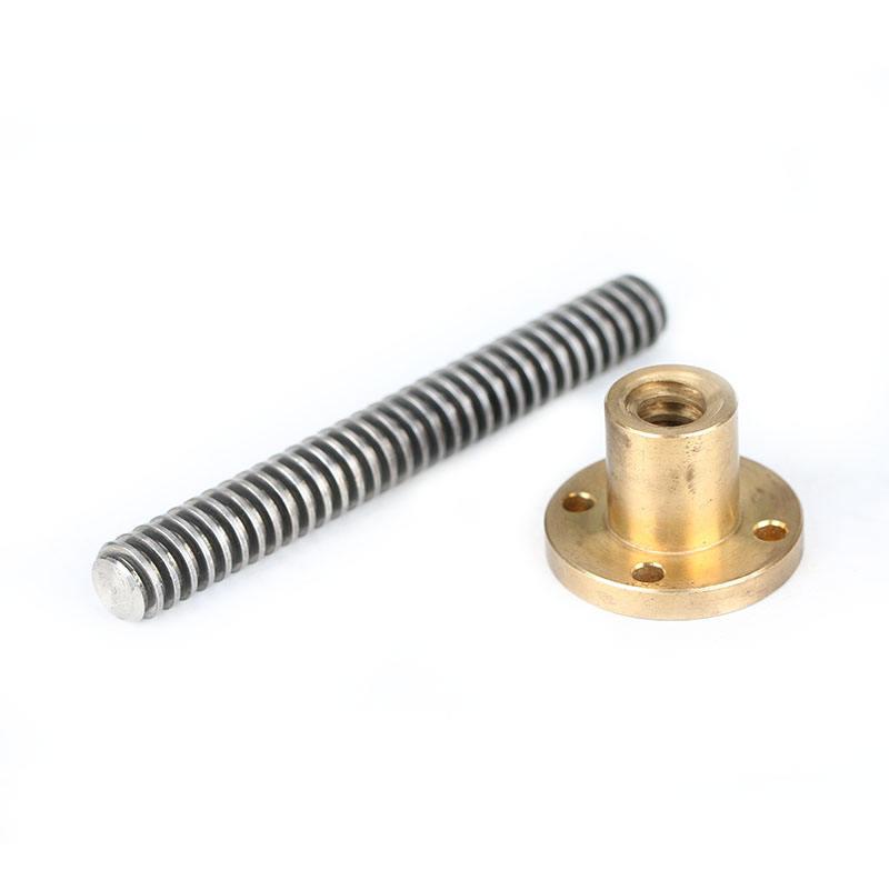
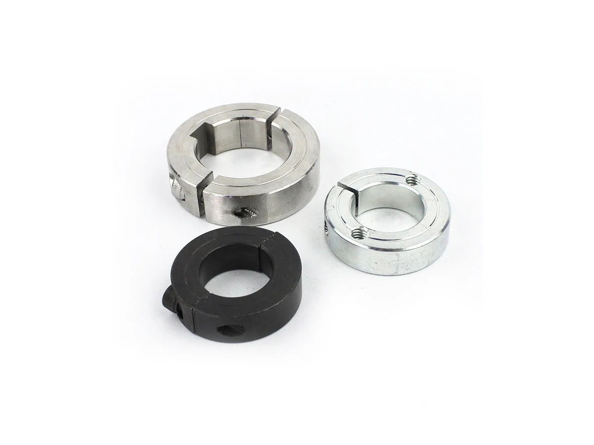
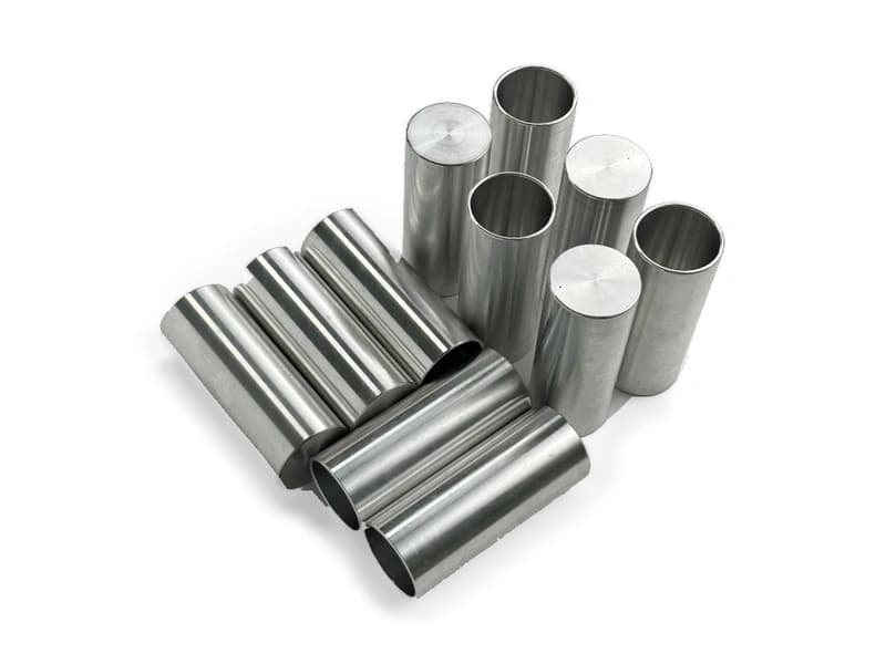
Use the dimensioned drawing to define these requirements. The photographs show real component geometry; they do not establish a standard size, material grade or tolerance.
- Mating diameters
- Identify each functional diameter, fit and surface finish alongside its mating component.
- Shoulders & axial lengths
- Dimension the position of each shoulder from the chosen datum and show the required face relationships.
- Runout & coaxial features
- State the datum axis, controlled surfaces and inspection requirement for rotating or mating features.
- Slots, flats & cross-holes
- Define feature width, depth, orientation and location relative to the shaft axis and shoulders.
- Threads & end features
- Provide thread designation, engagement length, chamfers and any end-face requirements.
- Radii, reliefs & edges
- Show transition radii, tool relief and edge-break requirements at mating interfaces.