
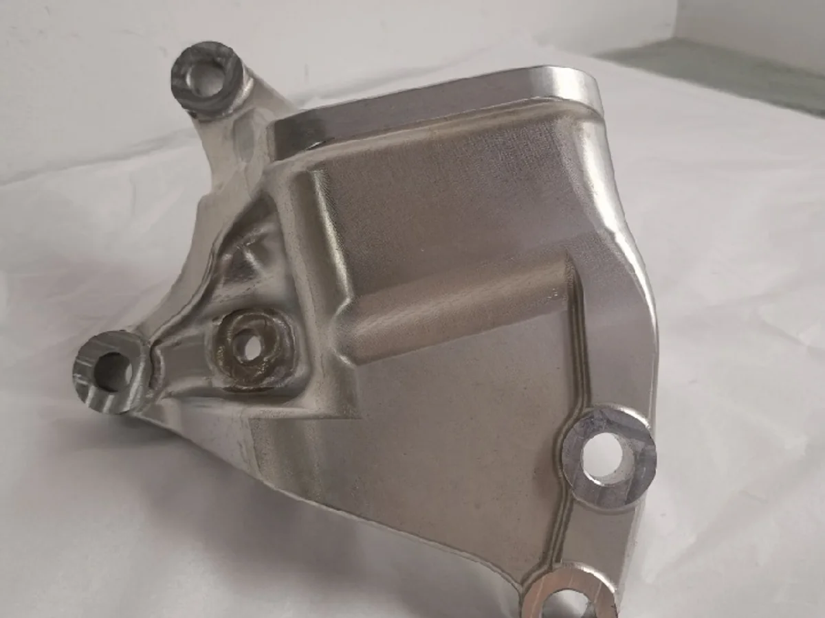
Motorcycle Mounting Components
Brackets and mounting structures with several bores, joining faces and access-sensitive geometry for assembly review.
01 / Automotive
Prototype and manufacturing support for custom automotive components, including machined mounting parts, mechanical housings, cylindrical components and lighting-style covers reviewed from customer drawings.
Upload Drawings & Request a Quote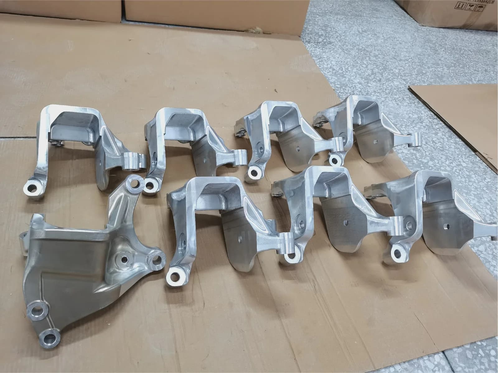
02 / Automotive Applications
Automotive product development often combines mounting, enclosure, rotational and appearance-led parts. Each category below is framed around visible geometry and the interfaces that need review.
Brackets and mounting structures with several bores, joining faces and access-sensitive geometry for assembly review.
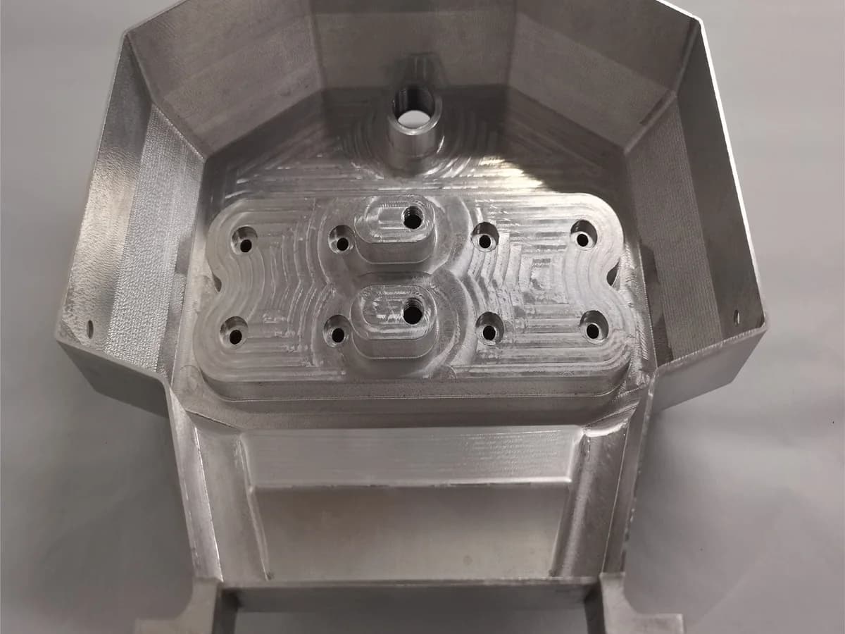
Custom electronic and mechanical enclosure concepts with openings, internal features and defined mating interfaces.
Round components with threaded regions, internal bores, radial features and functional face relationships.
Red translucent prototype covers used to review shape, appearance, edge condition and assembly fit before further development.
03 / Featured Product Examples
These photographs show real physical parts from the supplied project archive. Titles describe visible component form only; material, process sequence, finish and final vehicle application require project documentation.
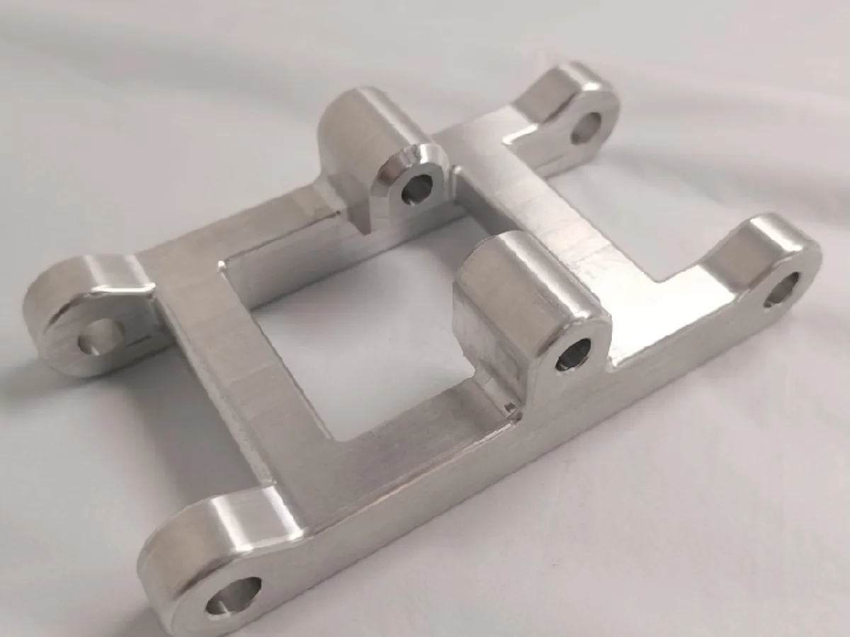
Open rectangular bracket with six mounting ears, multiple bores and stepped surfaces.
Review bore relationships, mating faces and tool access around the raised mounting features.
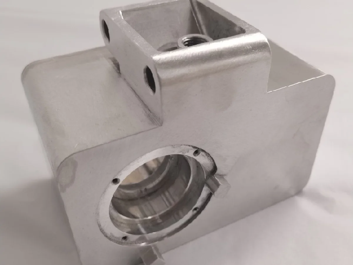
Box-form metal housing with a large circular opening, smaller holes and an upper mounting feature.
Define the primary locating surfaces, the central bore relationship and fastener access before release.
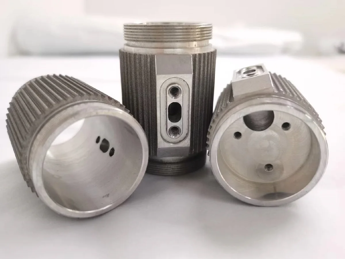
Three cylindrical components with external threads, ribbed outer surfaces and machined internal features.
Identify critical diameters, thread interfaces, radial features and the inspection datums that connect them.
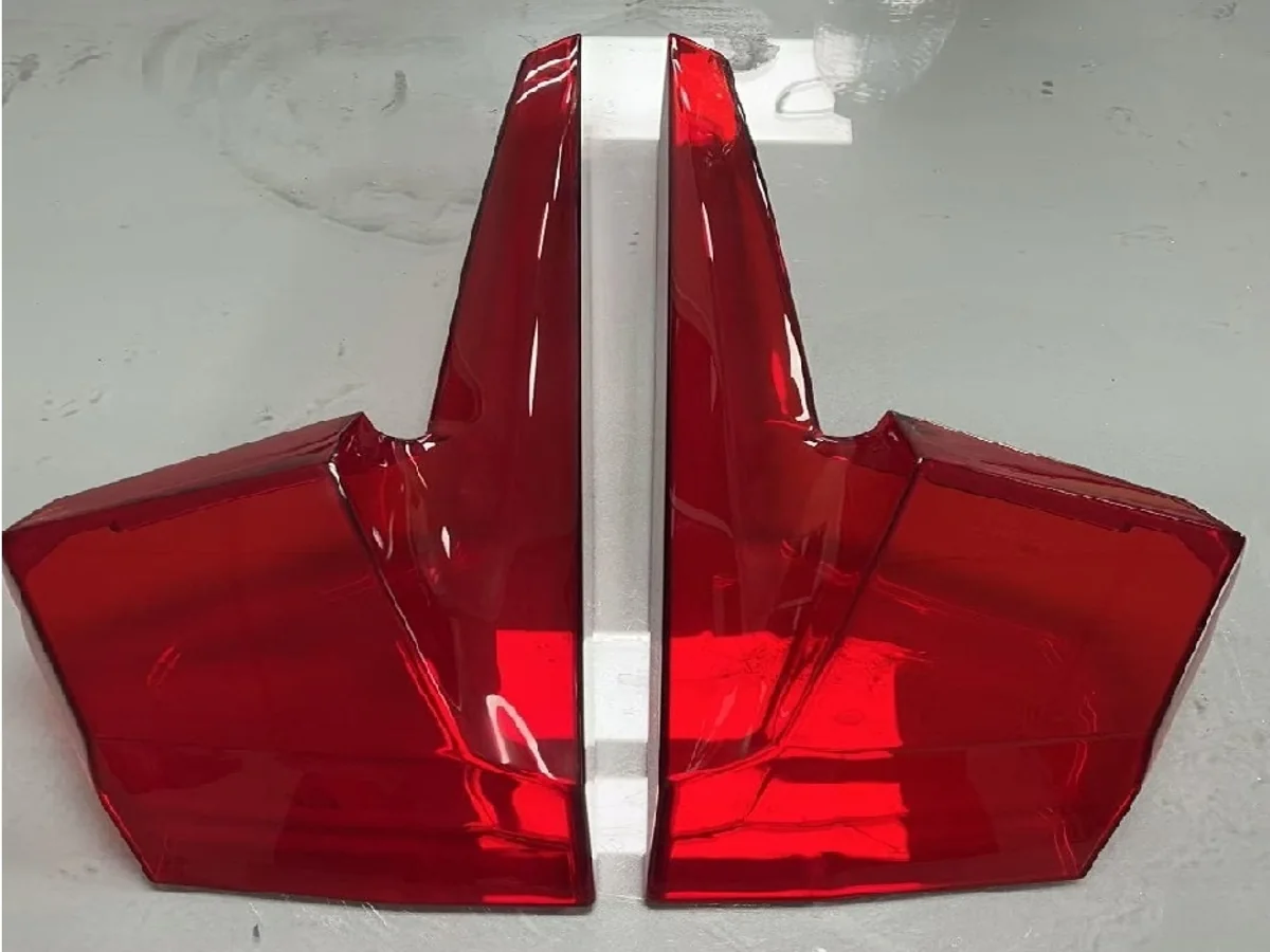
Paired red translucent covers with curved surfaces, tapered walls and a central separation line.
Review visible surfaces, edge protection, wall transitions and assembly interfaces against the approved design data.
04 / Engineering Considerations
Automotive prototype manufacturing starts with the way each part locates, clears adjacent geometry, presents visible surfaces and will be checked during development.
Document the surfaces and holes that locate the component in the final assembly instead of treating every feature as equally critical.
Use a clear datum strategy so hole position, face relationships and inspection setup follow the same assembly logic.
Allow for fasteners, adjacent parts, cables and installation movement when reviewing the available assembly envelope.
Review deep pockets, internal corners, side features and re-clamping needs before selecting the manufacturing route.
Separate appearance surfaces from functional faces and identify areas that may require protection during finishing.
For lighting-style or cosmetic prototypes, define the surfaces, edges and interfaces that control perceived quality and fit.
Identify the dimensions and relationships that need documented verification rather than applying one inspection level to every feature.
05 / Manufacturing Capabilities
Process selection follows geometry, material, quantity and validation stage. The six routes below support different parts of an automotive prototype or component program.
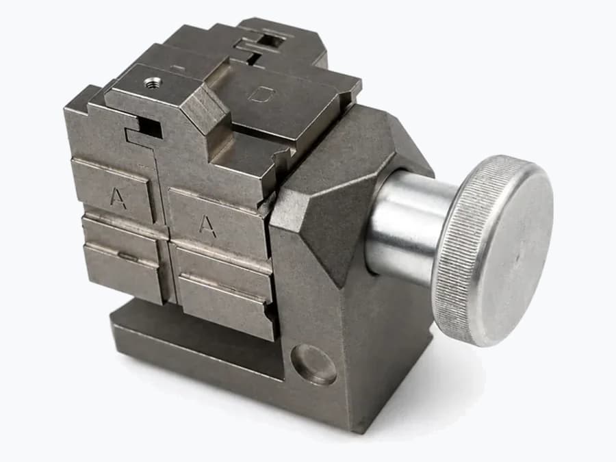
Machine brackets, housings, pockets, bores and mounting interfaces from released 3D data and controlled drawings.
Explore CNC Milling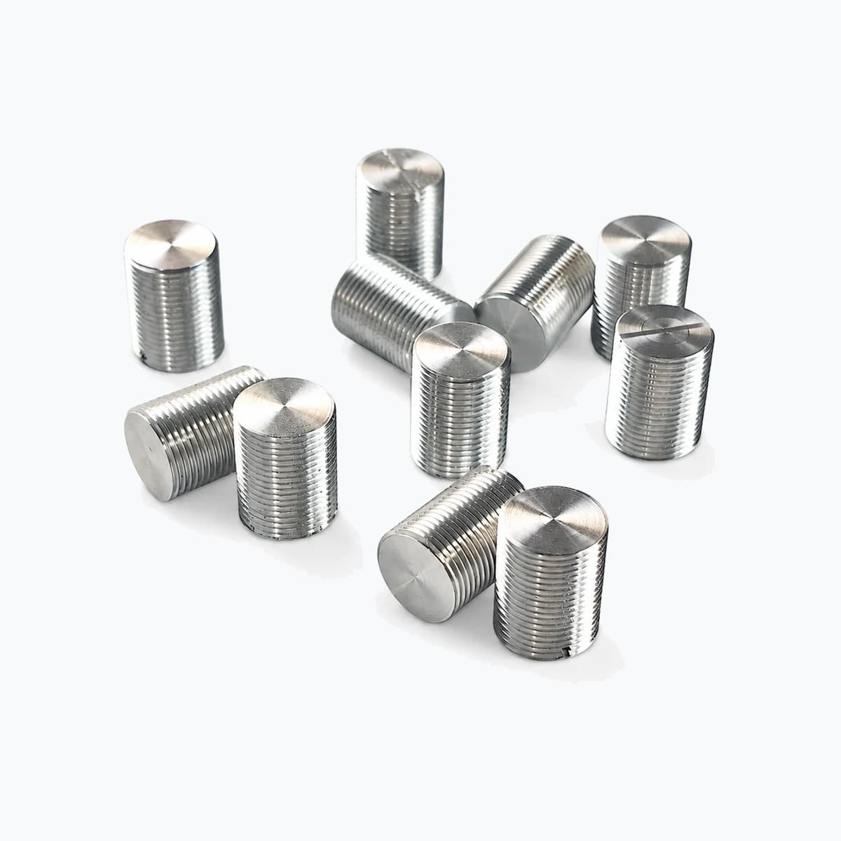
Produce cylindrical components with turned diameters, faces, threads and internal features where rotational geometry leads the route.
Explore CNC Turning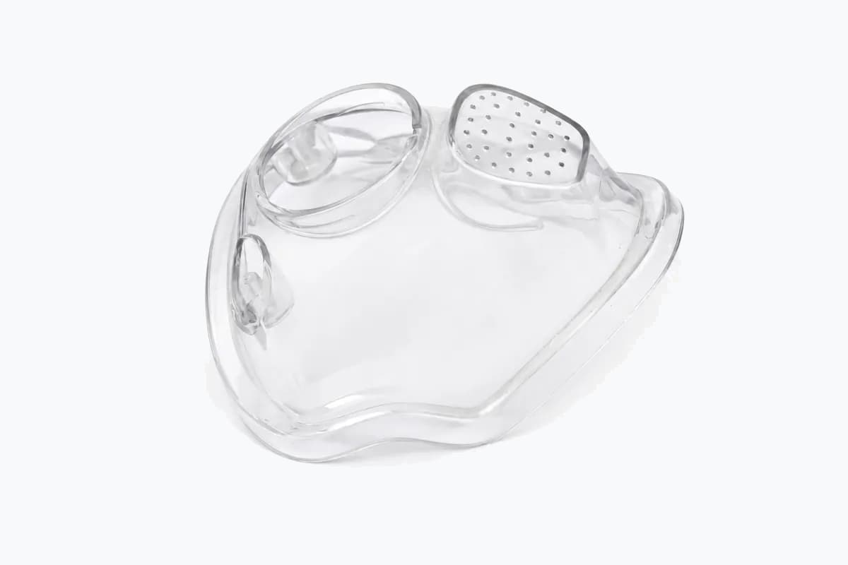
Build physical parts for geometry, fit, handling and assembly review while the automotive product design is still evolving.
Explore Rapid Prototyping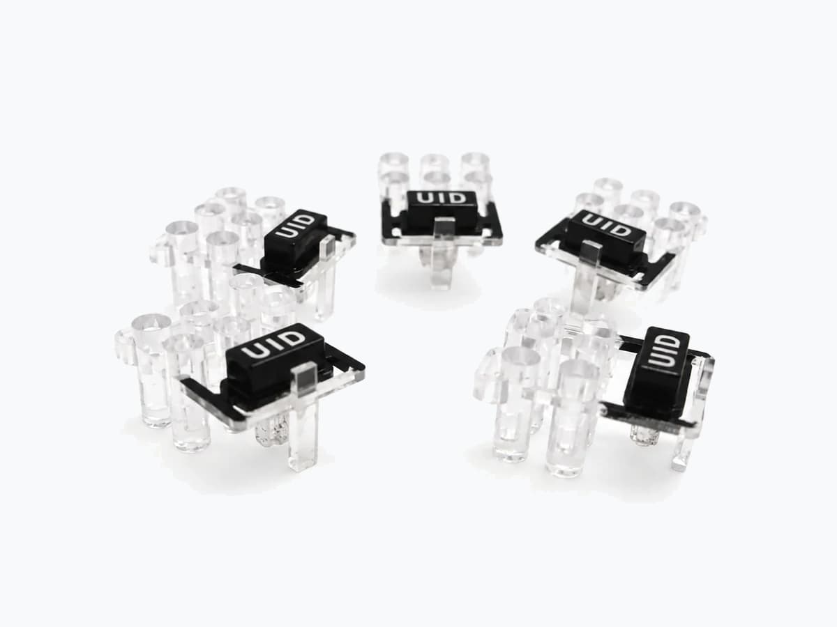
Replicate an approved master through silicone tooling when a project needs a small set of similar polyurethane prototype parts.
Explore Vacuum Casting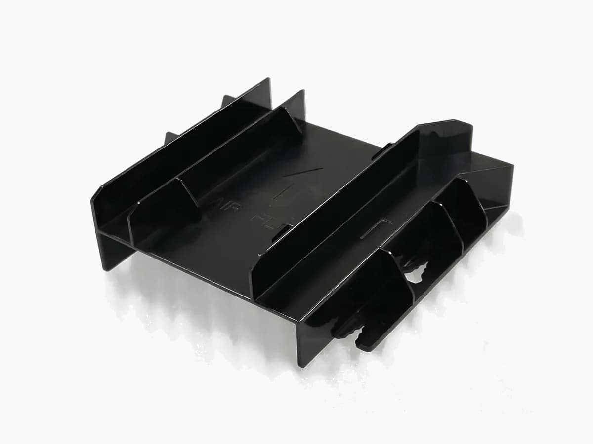
Review production thermoplastic parts when the design, material strategy and quantity justify dedicated mold tooling.
Explore Injection Molding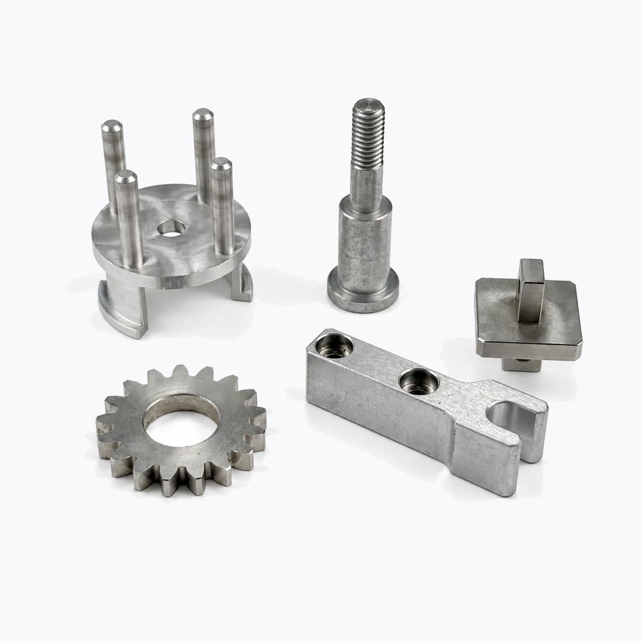
Coordinate appearance, preparation, masking and dimensional allowances with the base material and functional interfaces.
Explore Surface Finishing06 / Materials & Surface Finishing
Material and finish choices are confirmed from the functional requirement and the selected manufacturing route. No material or optical performance is inferred from the photographs.
Final metal selection should follow the released drawing, functional environment, weight, wear and finish requirements.
Plastic or polyurethane selection depends on the intended validation purpose, geometry and required behavior; no pictured material is inferred.
Finishing compatibility and dimensional allowance are confirmed against the selected material and project documentation.
07 / Prototype to Production
A controlled path keeps design data, physical fit, inspection feedback and production planning aligned as the automotive project matures.
Share 3D CAD, dimensioned drawings, expected quantity and the interfaces that matter in the product assembly.
Review geometry, validation purpose, material preferences and production stage before choosing a suitable route.
Manufacture physical development parts using the agreed data, route and project-specific review criteria.
Evaluate mounting, clearance, mating features, appearance and identified dimensions against the approved information.
Incorporate approved findings and review the appropriate path for low-volume or repeat manufacturing.
08 / Engineering FAQ
Practical answers for engineering and procurement teams preparing automotive prototypes, custom housings and machined parts for review.
AUTOMOTIVE PRODUCT DEVELOPMENT
Share your CAD files, drawings, quantity and project requirements for a manufacturing review.
Upload Drawings & Request a Quote