
Production Material Matters
Use the actual thermoplastic family when long-term mechanical, chemical, thermal or cosmetic behavior is part of the product requirement.
- End-use resin
- Mechanical behavior
- Chemical environment
- Thermal requirement
Manufacture repeatable thermoplastic parts through an engineered molding route built around tooling, material, geometry, surface requirements and production volume.
HERUIYUN reviews wall thickness, draft, ribs, bosses, gates, parting lines, undercuts, inserts, resin behavior and critical dimensions before tooling is released.
Get Injection Molding Quote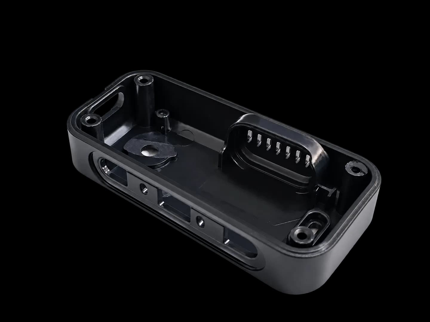
Injection molding is not one tooling strategy. The right route depends on product maturity, expected volume, material, hardware integration, cosmetic requirements and how much production risk has already been retired.
REPEAT PRODUCTION
Production tooling and repeat molding for thermoplastic parts where geometry, material, surface requirements and critical interfaces are sufficiently mature.
BRIDGE / PILOT
A faster tooling route may be reviewed for late-stage functional validation, pilot builds and bridge production before long-term tooling becomes appropriate.
COMPONENT INTEGRATION
Pre-positioned metal or other compatible inserts may be integrated into the molded part where retention, load direction and tooling access are defined.
MULTI-MATERIAL FUNCTION
A second molded material may be added to a compatible substrate for grip, sealing, protection or other combined-material functions.
Material bonding, mechanical retention, tooling and production sequence are confirmed project by project.
Injection molding becomes the stronger route when the project has moved beyond one-off validation and the manufacturing system must repeatedly produce the same geometry, material behavior and assembly interfaces.
Use the actual thermoplastic family when long-term mechanical, chemical, thermal or cosmetic behavior is part of the product requirement.
Tooling and process control become valuable when the same part must be reproduced consistently rather than rebuilt individually.
Tool investment becomes more appropriate as the design stabilizes and expected production volume supports a repeat molding route.
Finalize visible surfaces, textures, insert locations and mating geometry before the tool becomes the production reference.
Tool material, cavity layout, side actions, cooling, maintenance and expected production stage should be reviewed together before the mold is released.
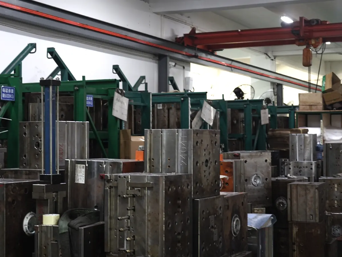
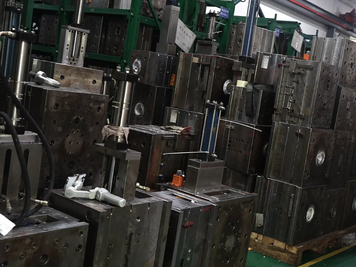
Aluminum, P20-type steel or other project-specific tool materials may be reviewed according to product stage, resin, surface requirement and expected production plan.
Single-cavity, multi-cavity and family-mold approaches should be evaluated around part geometry, demand, balance and process consistency.
Slides, lifters and other mechanisms can release undercuts but add tooling and maintenance complexity.
Expected tool life depends on tool material, resin, geometry, cycle conditions, maintenance and production requirements.
Repeat production depends on maintaining the approved tool, process settings and revision control over the product lifecycle.
A molded part should demonstrate more than appearance. Ribs, bosses, openings, mating interfaces, surface consistency and repeat production all contribute to whether the tool is ready for continued manufacturing.
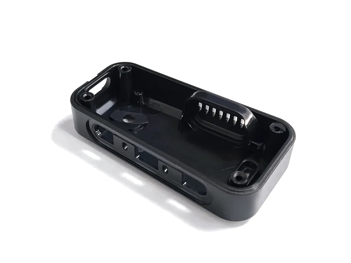
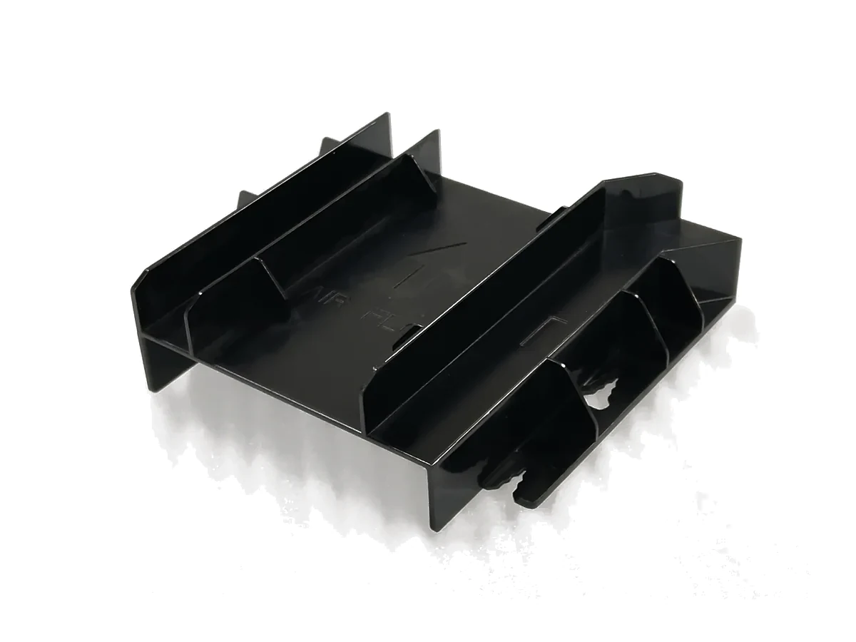

Material selection should follow mechanical, thermal, chemical, dimensional, cosmetic and regulatory requirements rather than one generic production-plastic specification.
A general-purpose engineering thermoplastic often reviewed for housings, enclosures and parts requiring a practical balance of rigidity, impact behavior and cosmetic finish.
Reviewed where toughness, dimensional stability or transparency are relevant, with PC-ABS offering a different balance of processing and impact behavior.
Reviewed for mechanically loaded parts, wear-related features and engineering components where grade-specific moisture and dimensional behavior are understood.
Reviewed for low-density, chemical-resistant or flexible-product requirements depending on grade and geometry.
Reviewed for low-friction mechanical components, moving interfaces and dimensionally controlled functional parts.
Reviewed for engineering components where dimensional, electrical or thermal requirements justify the material family.
Reviewed where optical appearance, transparency and surface quality are important.
Reviewed for demanding thermal / chemical applications where the project requirements justify a higher-performance resin system.
Other resin families and grades are reviewed against geometry, finish, production conditions and end-use requirements.
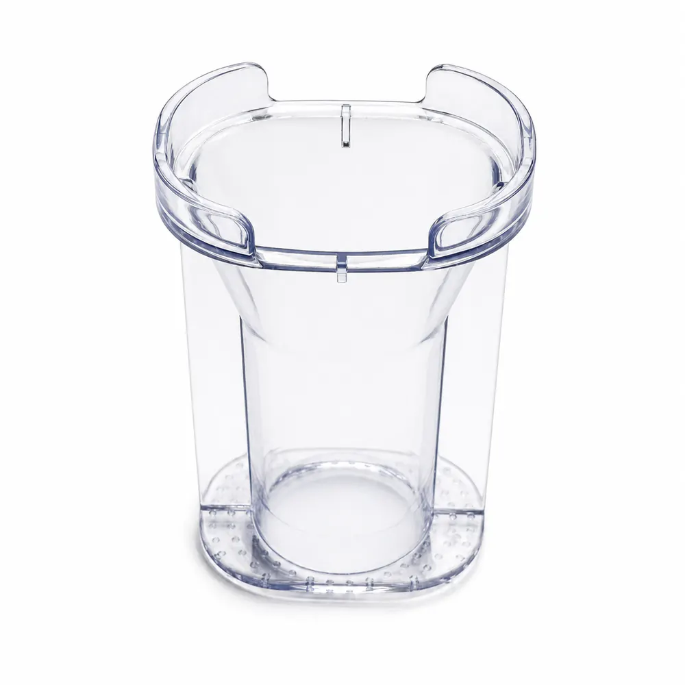
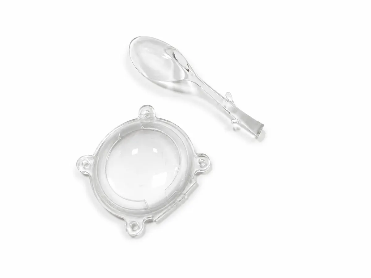
Final resin availability and molding suitability are confirmed after grade, geometry, surface and production review.
Every tooling decision is affected by the part geometry. Uniform material distribution, practical ejection and controlled local mass reduce the risk of sink, warp, difficult tooling and unstable repeat production.
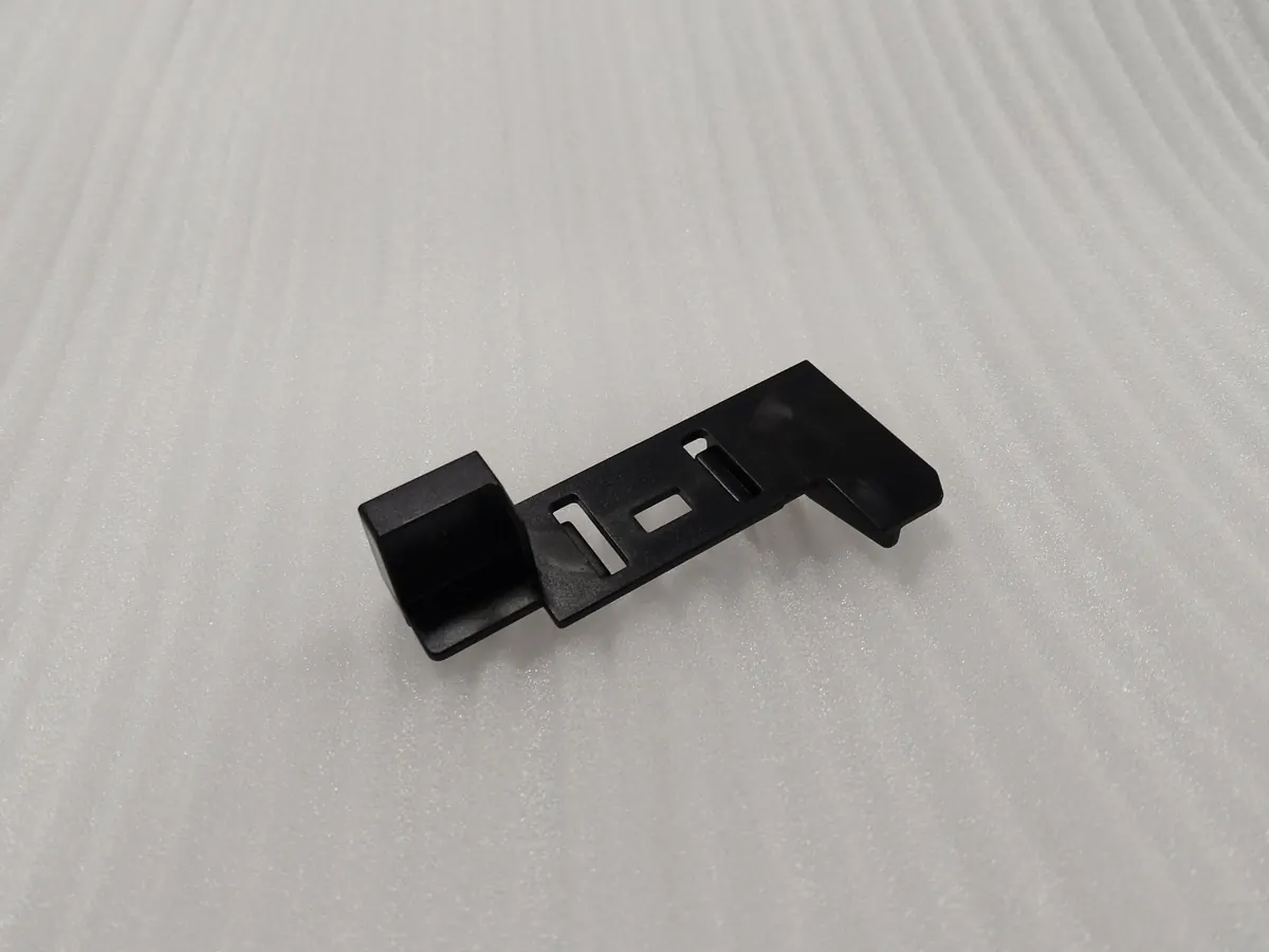
Keep wall distribution as consistent as practical and avoid unnecessary local mass that can cool and shrink differently from adjacent geometry.
Provide sufficient draft for reliable ejection, especially on deeper or textured surfaces. Final draft is confirmed according to geometry, material and finish.
Use ribs to improve stiffness without simply increasing global wall thickness, and review rib thickness to reduce sink risk.
Support screw and assembly features without creating isolated heavy sections or weak unsupported posts.
Undercuts may require slides, lifters, hand loads or part redesign and should be reviewed before tooling complexity is locked in.
Use smooth transitions to support flow, reduce sharp stress concentration and improve tool manufacturability.
Gate vestige, parting lines, ejector marks, knit lines and vents are part of the manufacturing architecture. Their location should be planned around visible surfaces and critical interfaces rather than discovered after T1.
Gate strategy influences fill direction, local vestige and material-flow behavior.
The mold split creates a visible line that should be positioned away from critical cosmetic or sealing surfaces where practical.
Ejection requires contact with the molded part and may leave local marks that should be planned on non-critical surfaces.
Flow fronts may rejoin around openings or complex geometry, creating local lines that should be reviewed where strength or appearance matters.
Air needs controlled escape paths to reduce burn, incomplete fill and trapped-gas risk.
Pre-positioned metal or compatible components can be molded into the plastic part when retention, load direction, tool access and final assembly requirements are defined.
Insert feasibility and installation sequence are project-specific.
A secondary material may be molded over a compatible substrate to create grip, sealing, impact protection or another combined-material function.
Material compatibility, chemical bonding, mechanical interlock and molding sequence must be confirmed before tooling release.
Tool surface and resin behavior define the base appearance before secondary finishing.
Polished or stoned mold surfaces may be reviewed according to the required gloss, texture and resin behavior.
Project-specific texture may be applied through the tool where draft and geometry support clean release.
Secondary paint or coating may be reviewed where the molded surface alone does not meet color, appearance or environmental requirements.
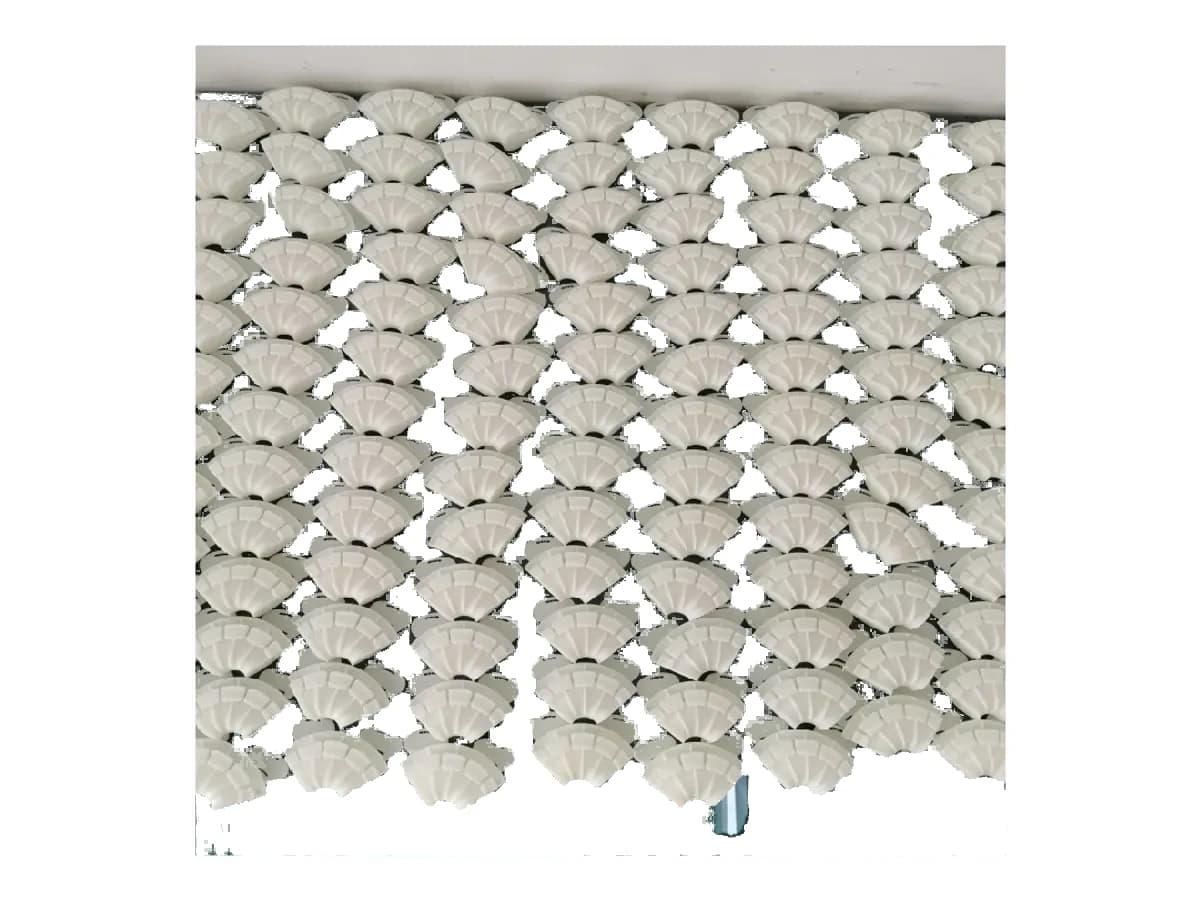
Selected molded components may receive electrostatic flocking or other project-specific secondary finishing where the substrate and surface-preparation route are compatible.
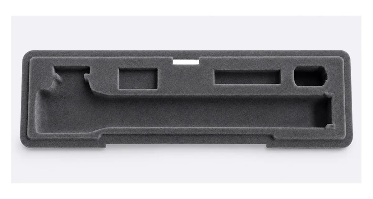
Injection molding dimensional capability is the result of resin shrinkage, wall distribution, tool construction, flow orientation, cooling and the location of critical assembly interfaces.
Each resin family and grade has its own molding and shrink behavior that must be considered during tool design.
Uneven material mass can cool and shrink differently, increasing sink and distortion risk.
Flow direction can influence filling, fiber orientation where applicable, weld lines and local dimensional behavior.
Cooling strategy affects cycle stability, part release and final warpage.
Tool stiffness, cavity construction and process repeatability influence how accurately the molded part tracks the approved design.
Mating features, holes, inserts and assembly datums should be identified on the drawing and prioritized during T1 review.
Final achievable tolerance is confirmed after resin, geometry, tooling and critical-dimension review.
Review geometry, resin, quantity, critical dimensions, cosmetic zones, inserts and production objectives.
Confirm mold material, cavity approach, side actions, gate / parting strategy and the production stage the tool must support.
Manufacture the approved tool and prepare the process for initial molding trials.
Mold initial samples to evaluate fill, ejection, dimensions, appearance and assembly interfaces.
Review T1 findings, complete approved tool or process corrections and freeze the production-ready revision.
Run the approved molding process and inspect the characteristics defined by the drawing, quality plan and production requirement.
Not every product follows the same path. The manufacturing route should evolve as design uncertainty decreases, quantity rises and the need for production material, repeatability and tooling continuity becomes stronger.
Fast design iteration and geometry validation.
Repeated polyurethane prototype batches without hard production tooling.
Pilot / bridge molding where production-relevant thermoplastic behavior is needed before long-term tooling.
Repeat production after geometry, material and key interfaces are sufficiently mature.
Longer-term tooling strategy aligned to forecast volume, resin, quality and maintenance requirements.
Evaluate the first molded samples before the tool becomes the reference for repeat production.
Inspect drawing-defined dimensions and interfaces that control assembly and function.
Review visible surfaces, texture, color, gate / parting evidence and approved secondary finish.
Where inserts or hardware are present, verify their position, retention and relationship to molded geometry.
Confirm the molded component interfaces correctly with mating parts and hardware.
Monitor the production characteristics that must remain stable across repeat molding and future reorders.
Provide the latest solid model used to define the molded geometry.
Identify critical dimensions, tolerances, datums, inserts, cosmetic zones and inspection requirements.
Specify the required resin family, exact grade where mandatory, color and any mechanical / environmental requirement.
Provide initial quantity, expected repeat demand and development stage so the tooling route can be reviewed appropriately.
Define gloss, texture, paint, flocking, marking or other visible-surface requirements.
Provide the insert, substrate, hardware or second-material requirements where component integration is required.
Identify the assembly features that control fit, function or installation.
Answers are qualified around material, geometry, tooling and the production stage rather than universal molding promises.
HERUIYUN can review common thermoplastic families such as ABS, PC / PC-ABS, PA / Nylon, PP, PE, POM, PBT, PMMA, PPS and other project-specific resins. Final material availability and process suitability are confirmed according to grade, geometry, quantity, surface requirements and production conditions.
Vacuum Casting is useful for repeated polyurethane prototype batches from a master pattern. Injection molding becomes more appropriate when the project needs production thermoplastics, greater repeatability, higher sustained quantities or a long-term production tool.
Rapid tooling is a project-specific molding-tool strategy intended to support late-stage validation, pilot builds or bridge production before a longer-term production tool is justified. Tool material, expected life, cavity strategy and lead time are confirmed after engineering review.
Tool material and cavity strategy depend on part geometry, resin, expected production volume, surface requirements, cycle considerations, tool life and commercial objectives. Single-cavity, multi-cavity or family-mold approaches are evaluated project by project.
Yes, project-specific insert molding may be reviewed for threaded inserts, bushings, pins or other compatible hardware. Insert retention, load direction, position, material compatibility and tooling access must be defined before the mold is released.
Overmolding with flexible materials such as TPE or TPU may be reviewed where the substrate, second material, bonding strategy and geometry are compatible. Chemical bonding, mechanical retention and molding sequence must be confirmed for the selected material pair.
Dimensional capability is reviewed through the combined effects of resin shrinkage, wall distribution, gate and flow direction, cooling, tool construction and critical-interface location. Important dimensions should be identified on the drawing and confirmed during T1 and engineering review.
Initial T1 or first-article samples are reviewed for fill, ejection, critical dimensions, appearance and assembly requirements. Approved tooling or process corrections are then completed before the production-ready revision is released for repeat molding.
Upload your CAD and drawing for review of resin, wall geometry, tooling strategy, inserts, surface requirements, quantity and critical dimensions.