
Turn-Mill Components
Flanged connectors combining turned shoulders, milled faces and drilled features.
- Machining Features / Process
- Turning with secondary milling and drilling.
- Applications
- Automation · Assembly fixtures · Mechanical couplings
Explore turned interfaces, secondary machining features and material-specific requirements across three product groups.
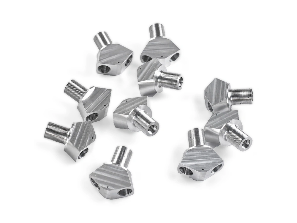
Rotational features combined with cross-axis bores, milled faces and compact functional details.
Flanged connectors combining turned shoulders, milled faces and drilled features.
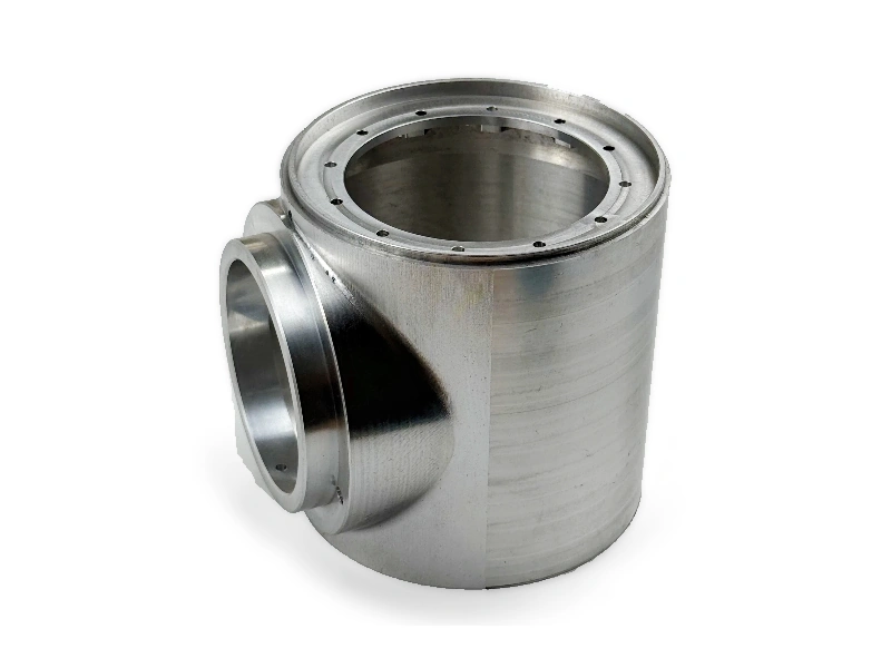
Cylindrical body with intersecting axial and transverse bores.
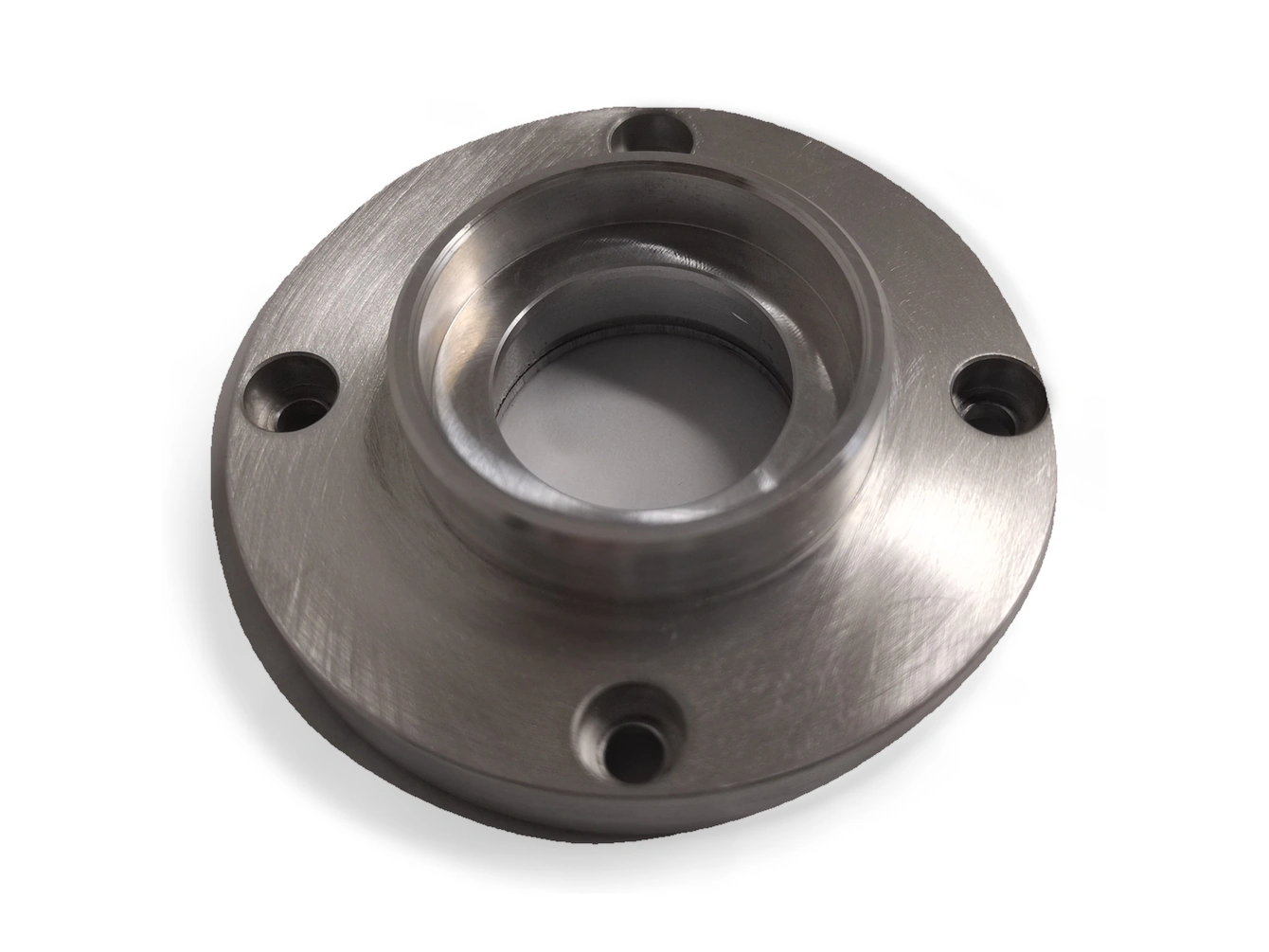
Stepped central bore, mounting face and an offset bolt-hole pattern.
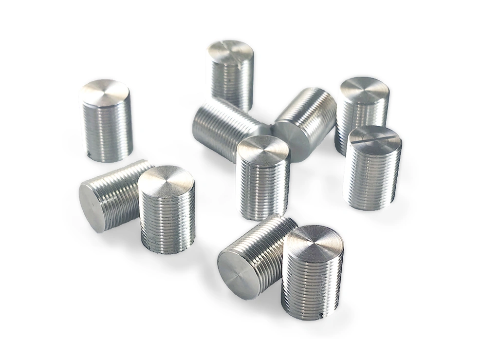
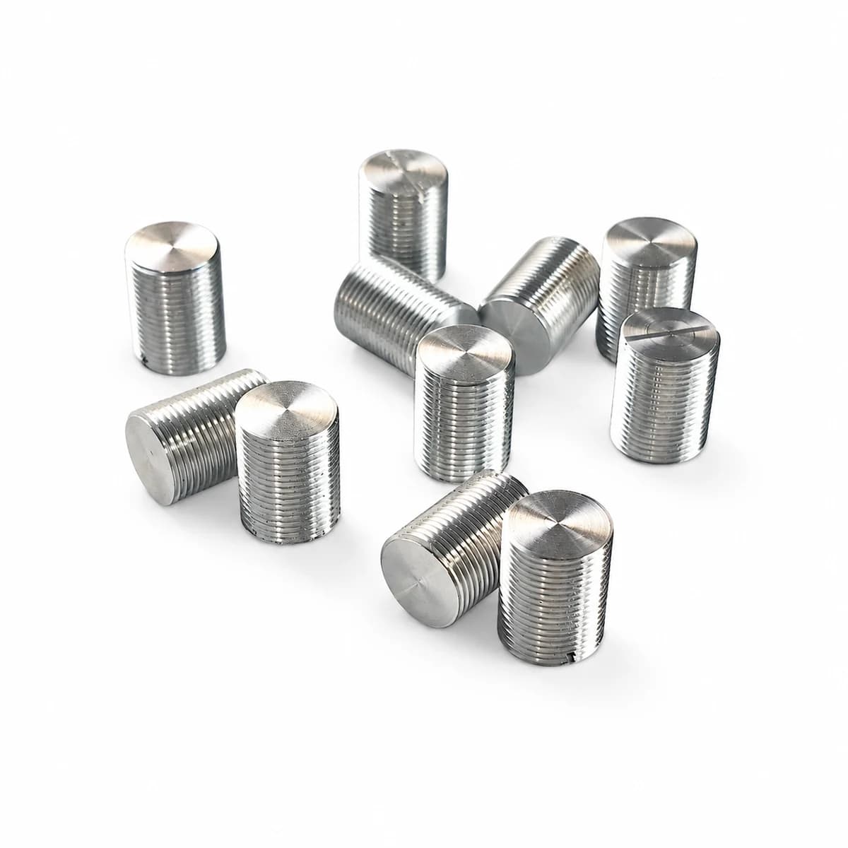
Compact cylindrical components with stepped ends and textured side features.
Shaft interfaces, slender wall sections and contoured profiles organized around the finished component.
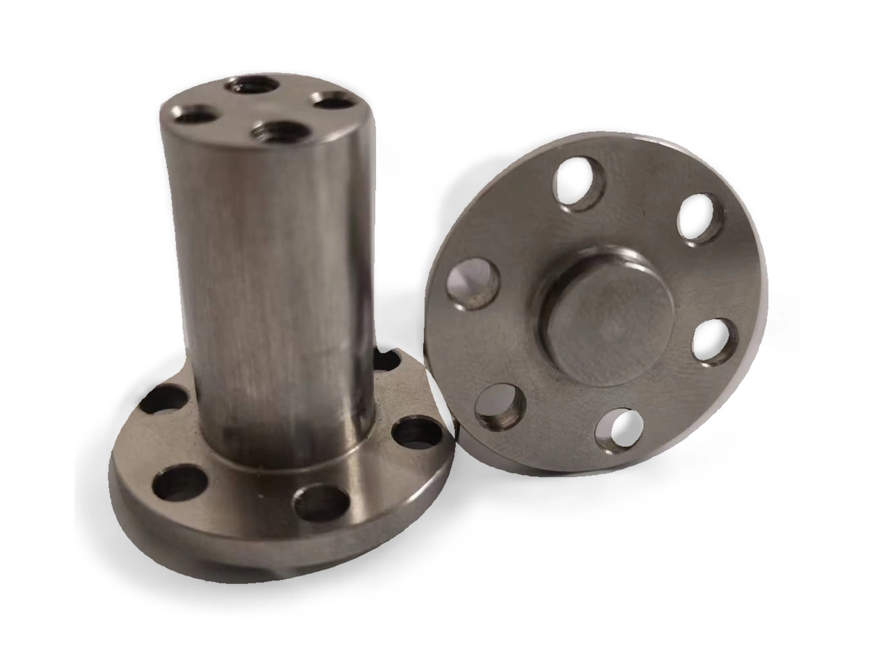
Flanged shaft and mating circular interface with concentric bores.
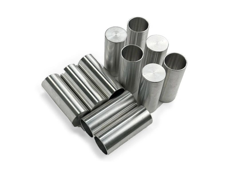
Open-ended sleeves with slender wall sections and internal cylindrical surfaces.
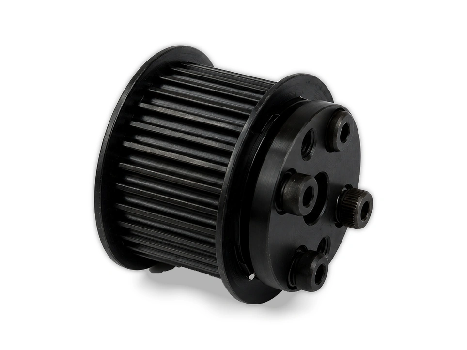
Toothed pulley geometry with a central bore and mounting features.
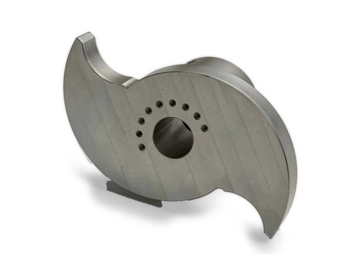
Contoured outer profile, central bore and a circular pattern of small holes.
Material categories are specified by alloy and condition. Photographs illustrate geometry, not material certification; magnesium alloy supply and machining controls require confirmation.
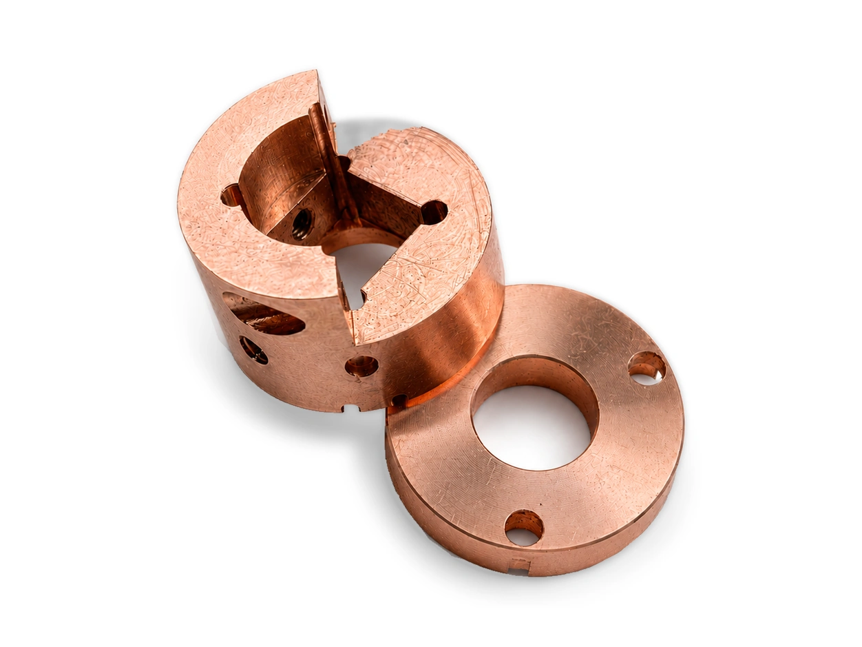
Split bushing and flange geometry with bores, slots and mounting holes.
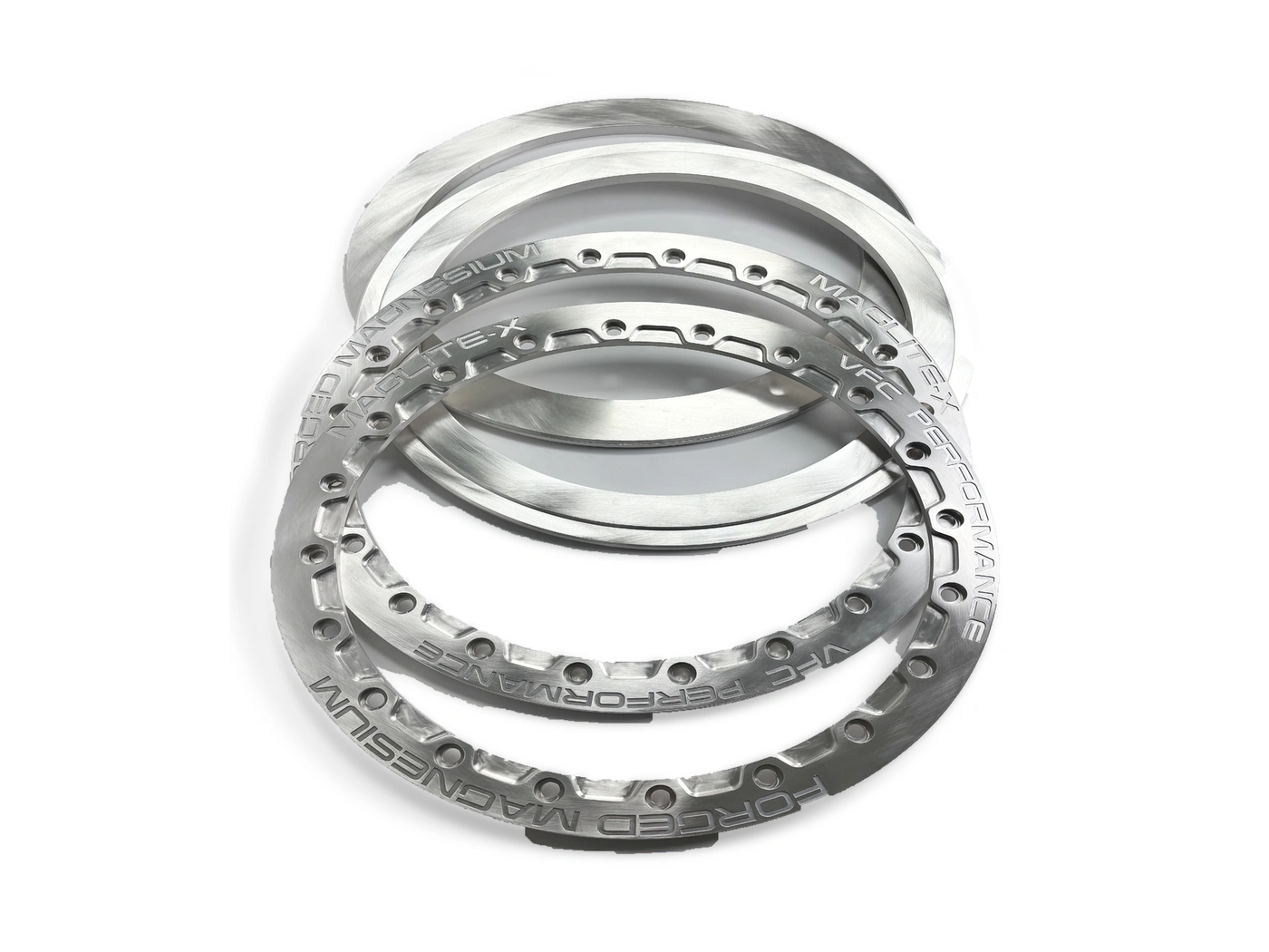
Thin annular mounting-ring geometry with repeated holes and local cutouts.
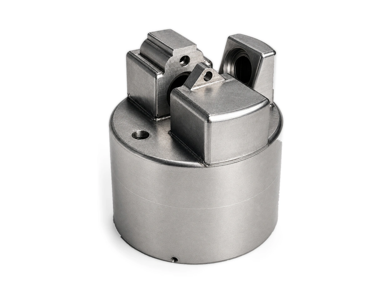
Stepped cylindrical base with drilled mounting features and milled upper faces.
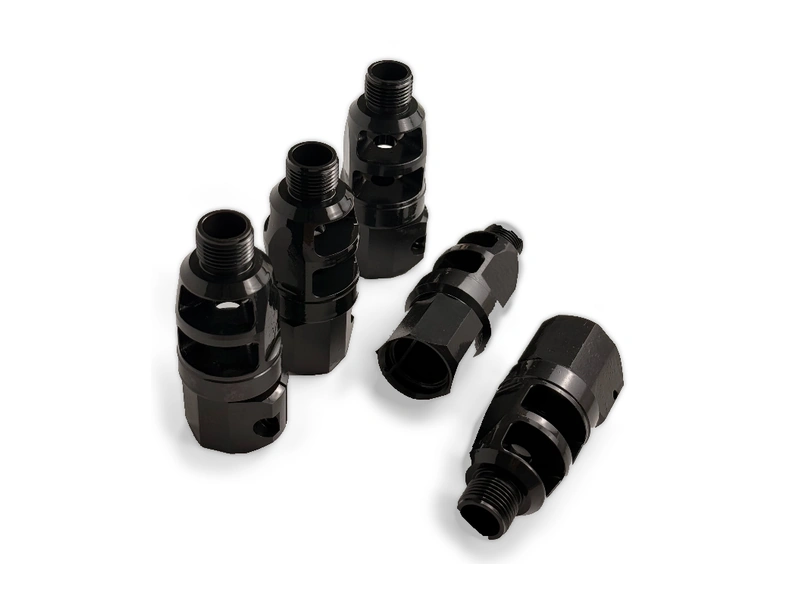
Precision cylindrical connectors with turned shoulders and secondary machined features.
Applications describe design contexts, not documented customer projects. Final material, machining route and inspection scope are agreed against the drawing.
Reference values depend on material, geometry, finish and inspection; ±0.005 mm applies to selected critical features subject to engineering review. Size is a machining-envelope reference, not a maximum turning diameter; diameter, length and schedule are confirmed in the quotation.
Practical design considerations for thin walls, shaft rigidity, concentric features, cross holes and secondary machining operations.
Conceptual engineering diagrams · Not to scale · No manufacturing limits implied
Provide usable clamping areas and balance wall thickness with diameter, length and material.
Check critical dimensions after unclamping.
Limit unsupported overhang and provide suitable support for slender shaft sections.
Identify chucking surfaces that may be marked.
Use a common datum axis for mating bores and outside diameters; identify the surfaces to check.
Specify runout separately from dimensional tolerances.
Make intersecting bores accessible for deburring and inspection.
Define permitted edge breaks at functional bore intersections.
Provide tool clearance at shoulders and define datum transfer between turning and secondary milling.
Protect functional edges and locating surfaces.
Apply the principles to the unsupported section and the tool approach.
Not Recommended
Long slender turned features can become less rigid during machining, increasing sensitivity to deflection and vibration.
Standard Practice
Where functional requirements allow, reduce excessive unsupported length or increase section stiffness to improve machining stability.
Not Recommended
Features located directly against restrictive shoulders can limit cutting-tool access and complicate machining.
Standard Practice
Appropriate relief or accessible feature transitions can provide the turning tool with a more practical machining path.
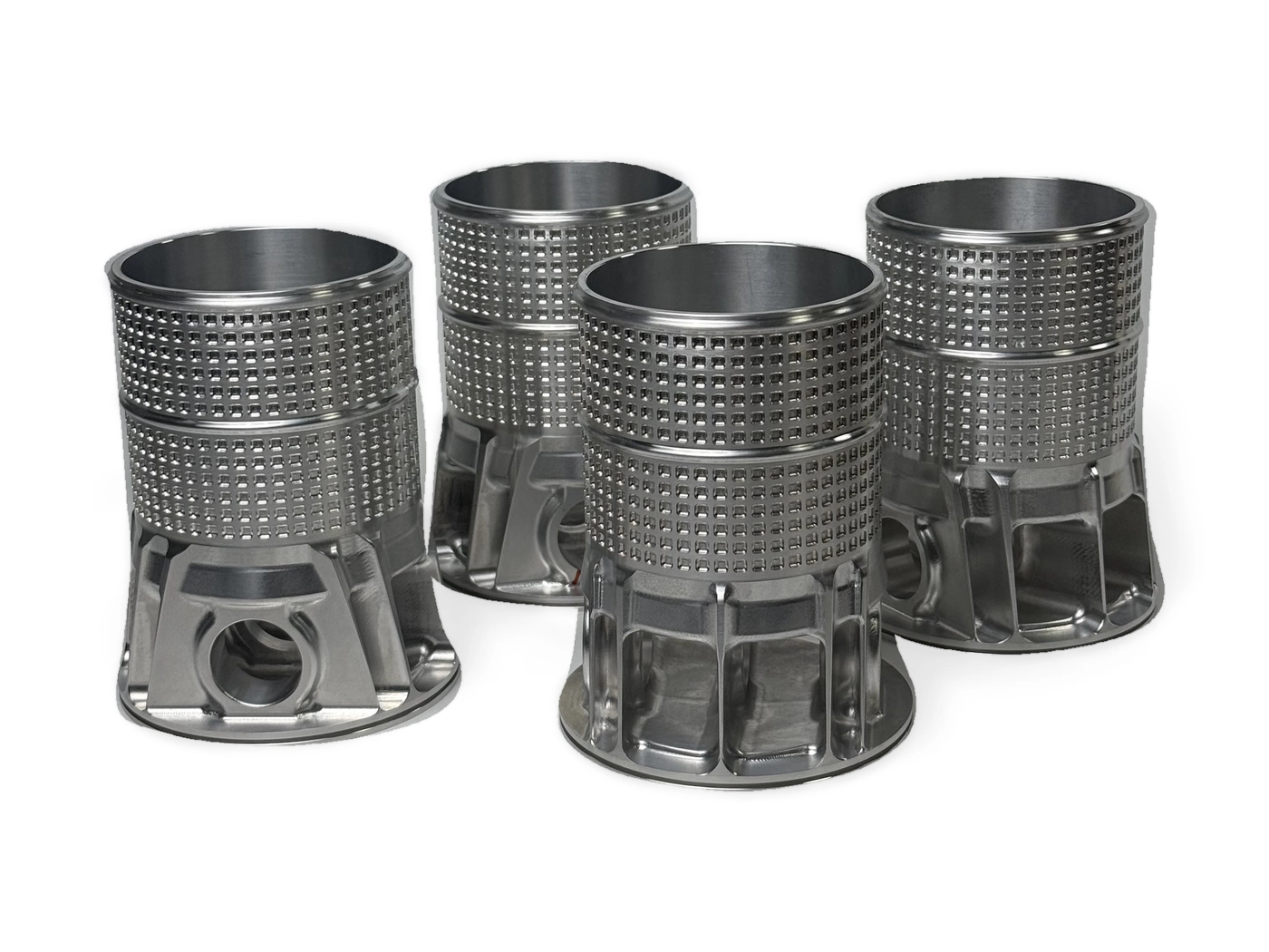
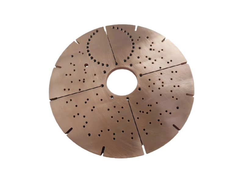
Material selection should balance mechanical requirements, machinability, surface condition and the functional needs of the finished component.
01 / Metals
02 / Engineering Plastics
Post-machining finishes may be selected for appearance, corrosion resistance, wear performance or other drawing-defined requirements.
Material and finish compatibility remains project-specific.
Explore Surface Finishing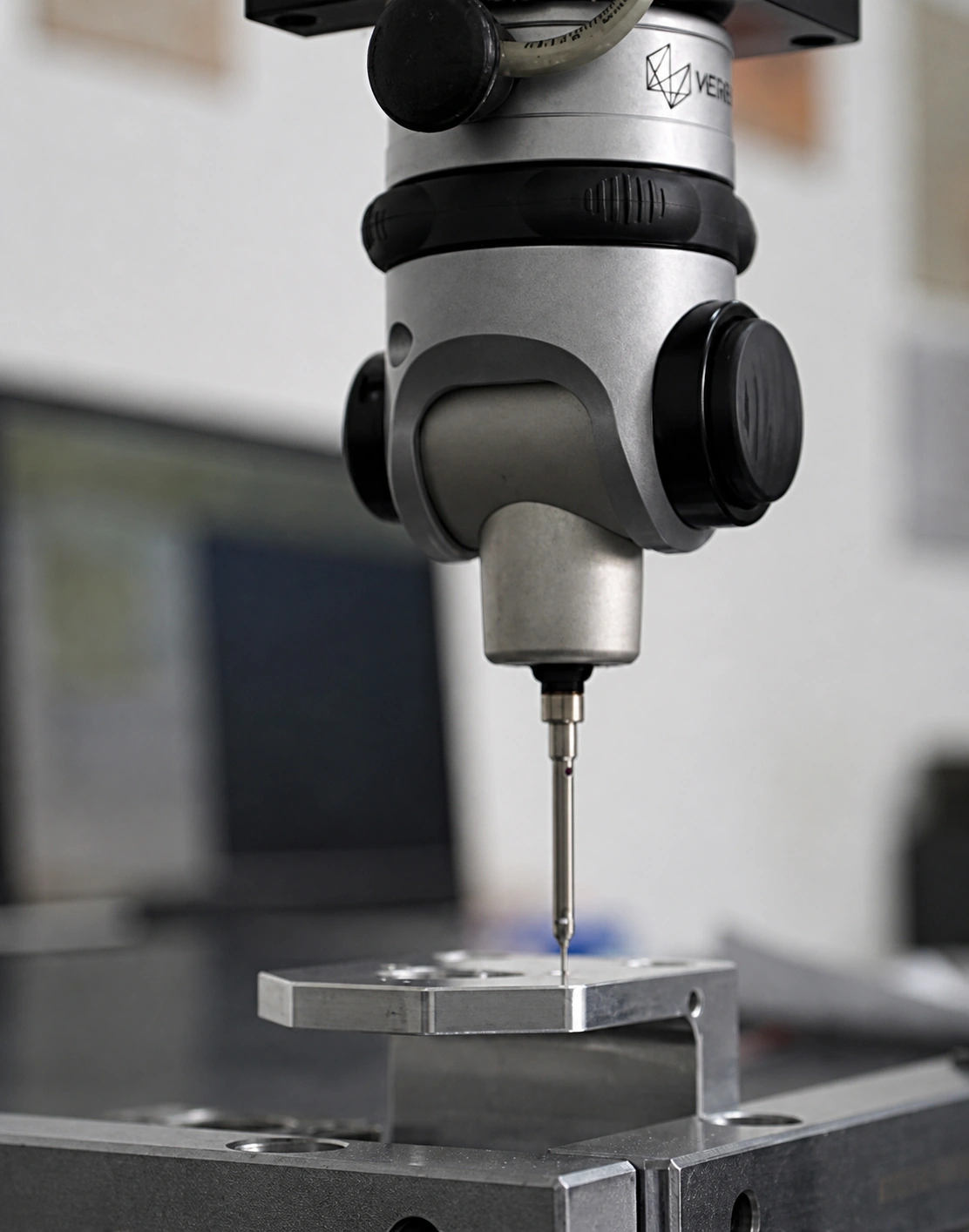
Agree dimensional checks, datum relationships, surface requirements and the required documentation before production. Inspection scope is defined for the project.
Review diameter relationships, tolerance requirements and manufacturing features before production planning.
Support development parts, low-volume builds and repeat manufacturing programs.
Coordinate dimensional inspection and material documentation according to agreed project requirements.
Upload your CAD files for engineering review and a project-specific CNC turning quote.