Corner Joint
Panels or flanges meeting at an angle where outside and inside access must be considered.

Join formed sheet-metal components into functional frames, housings and assemblies through reviewed welding and mechanical joining routes.
HERUIYUN evaluates material, thickness, joint geometry, weld access, fit-up, distortion risk, cosmetic requirements and downstream finishing before confirming the assembly route.
Get a Welding & Assembly Quote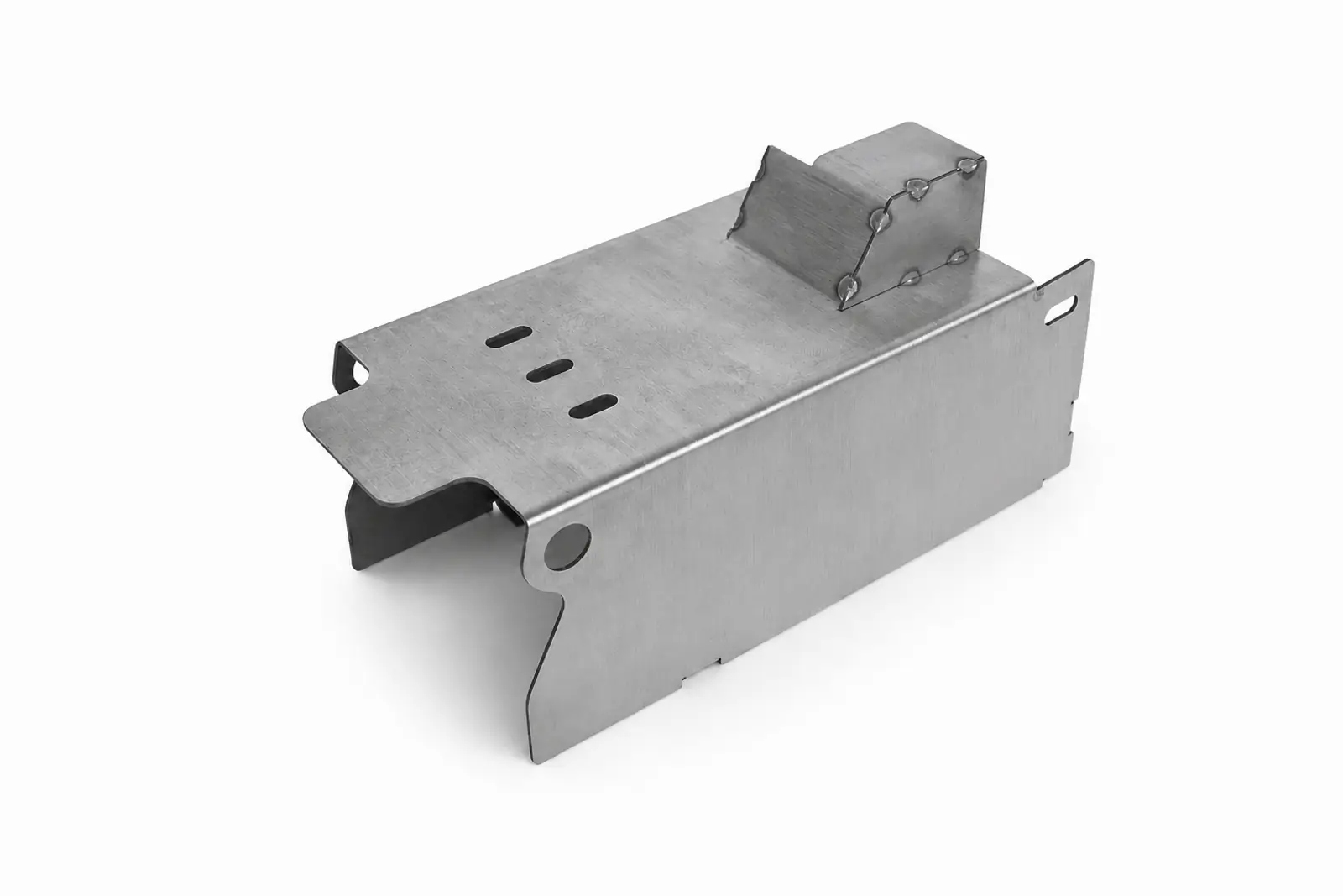
The correct joining route depends on material, thickness, joint geometry, structural intent, cosmetic requirements, access and whether the assembly must remain serviceable.
A controlled joining route for projects where weld placement, manual access and local heat input require careful review.
A practical joining route for suitable fabricated frames, structural sheet-metal components and repeat assemblies.
Localized joining of overlapping sheet components may be reviewed where material, thickness and joint geometry allow.
Rivets, threaded hardware and PEM-style fasteners can reduce heat input or improve serviceability where welding is not the best joining route.
Join multiple cut and formed components into one functional structure when separate parts must act as a single assembly.
Frames, chassis, housings and enclosure structures often require multiple panels or brackets to be joined after cutting and bending.
Add brackets, supports, mounting features or reinforcement geometry where a single formed blank is not practical.
A successful project may combine welding with rivets, PEM-style hardware or screws rather than forcing every connection into one joining method.
Joint geometry defines access, fit-up, heat placement and how the completed assembly can be inspected.
Panels or flanges meeting at an angle where outside and inside access must be considered.
One component meeting another surface at an angle, often requiring clear access along the intersection.
Overlapping sheet components joined along shared material area.
Adjacent edges or enclosure seams where fit-up, access, appearance and sealing requirements must be defined.
Real fabrication references show how cut and formed components move into joined housings, chassis and complete assemblies.
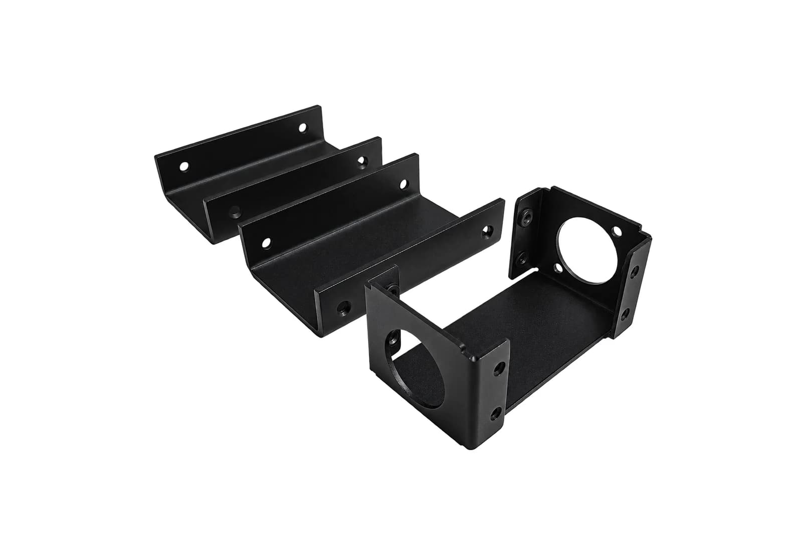
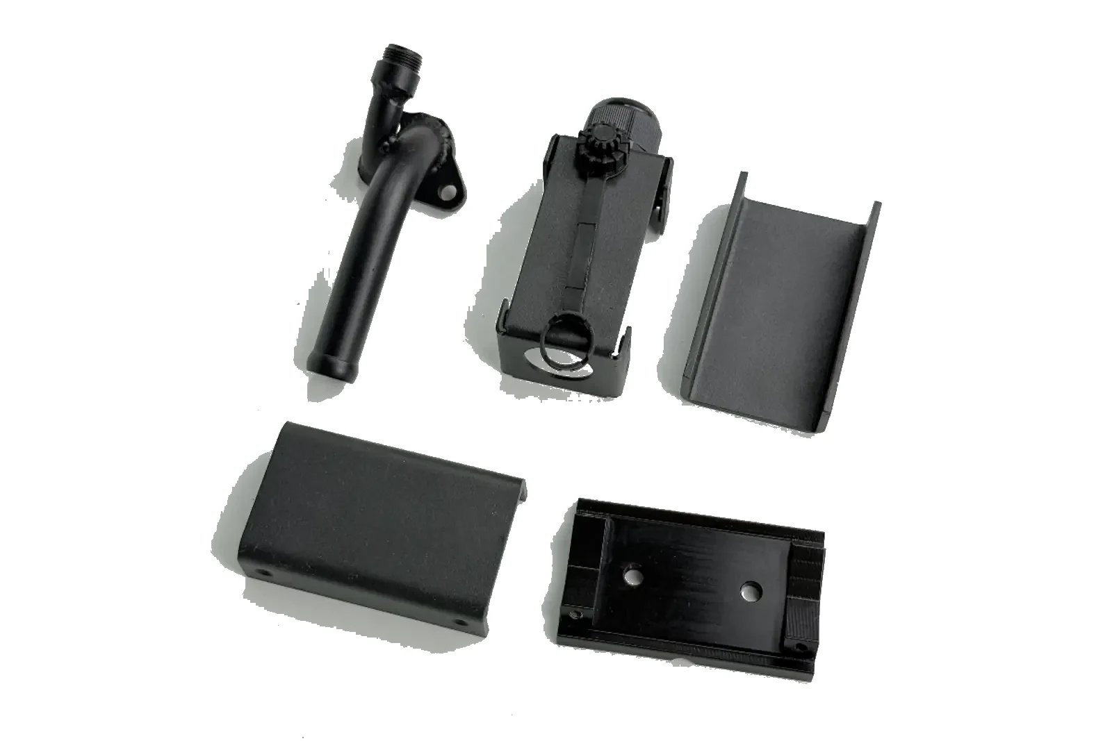
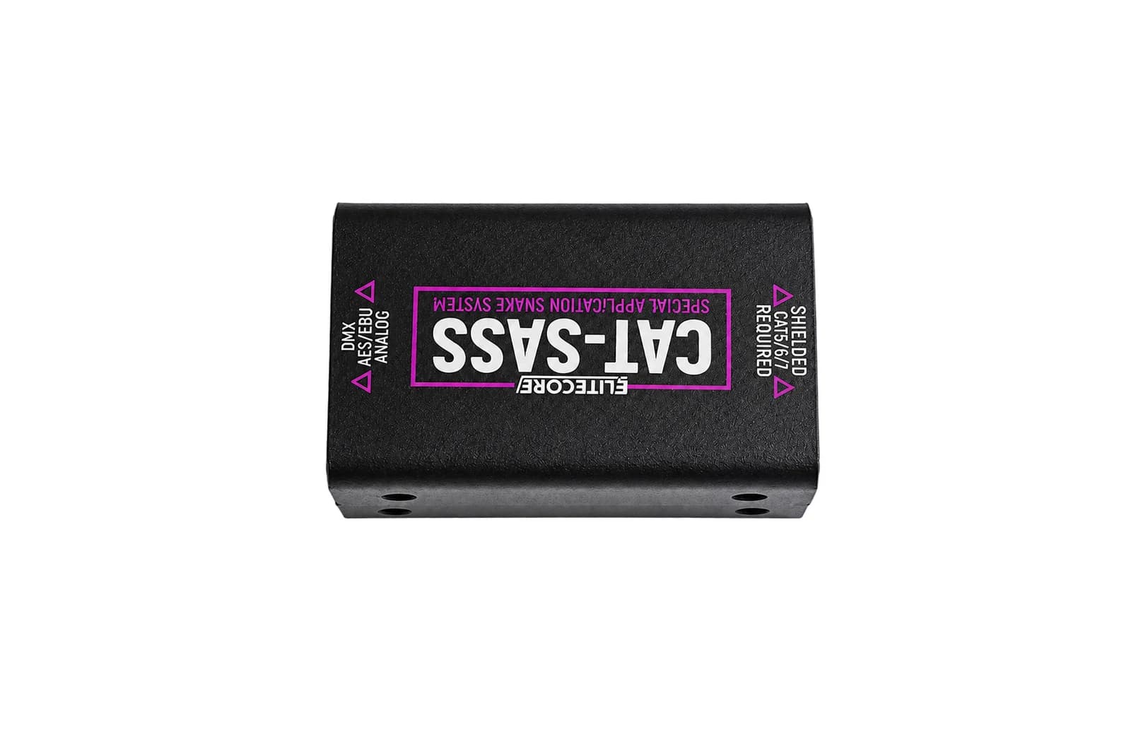
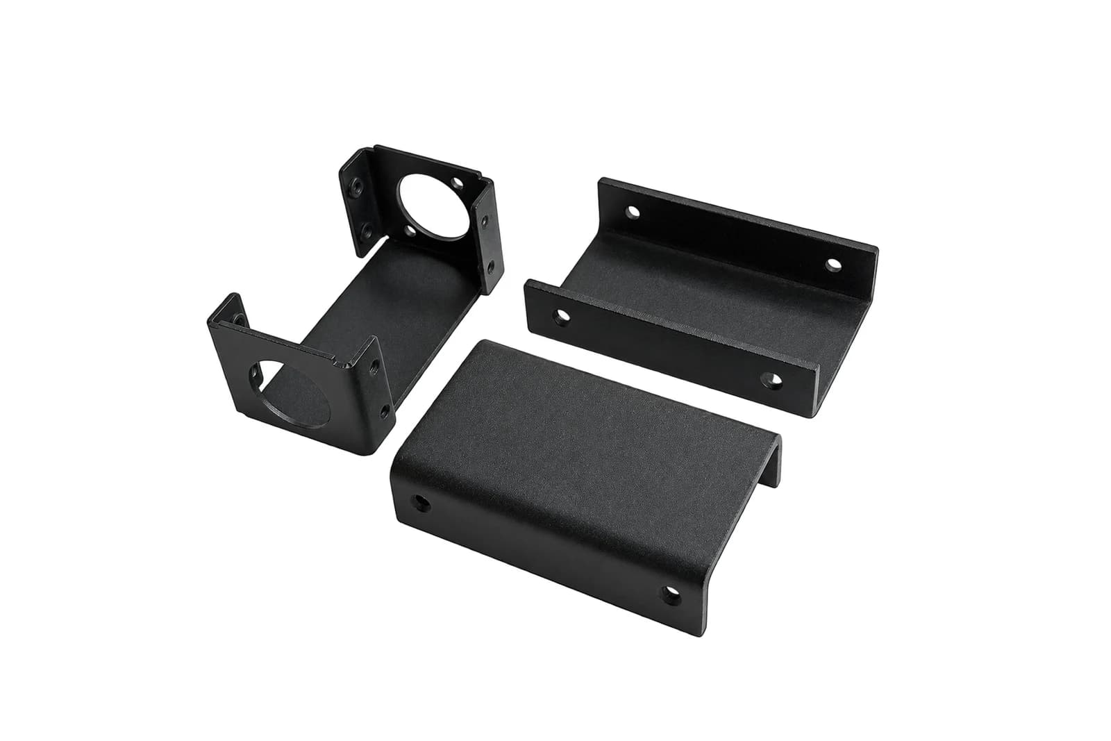
Joint access and assembly order should be reviewed before parts are locked into a closed geometry. A weld that is visible in CAD may become unreachable after another panel or flange is installed.
Welding introduces concentrated heat. Thin sheet, long seams, asymmetric geometry and repeated welds can move an assembly away from its nominal CAD shape if the process route is not planned around distortion.
Thin panels and large flat surfaces can bow or oil-can when heat is introduced unevenly.
Weld metal and surrounding material contract during cooling and can pull components out of alignment.
The material adjacent to the weld experiences a thermal cycle that can affect local appearance and behavior.
Long or multiple welds can accumulate dimensional movement across a frame, chassis or enclosure.
Grade examples
Aluminum joining requires review of alloy, temper, thickness, heat input, filler strategy and final cosmetic / finishing requirements.
Grade examples
Stainless assemblies require control of heat input, distortion, discoloration and post-weld surface expectations.
Grade examples
A common route for fabricated brackets, frames, chassis and assemblies that may later receive grinding, cleaning or protective coating.
Availability
Pre-coated or plated sheet requires special process review because joining heat can affect coatings, fumes, local corrosion protection and downstream finishing.
Availability
Joining suitability is reviewed individually because thermal behavior and material combination can substantially affect the manufacturing route.
Material combination, thickness, surface condition and joining suitability are confirmed before quotation.
Review cut and formed parts, materials, critical interfaces and whether each component is ready for joining.
Confirm joint locations, functional requirements, access, cosmetic zones and any inspection or sealing requirements.
Plan locating surfaces, assembly sequence and fixture strategy before heat or permanent joining is introduced.
Execute the approved welding or hardware route according to access, material and assembly requirements.
Perform approved grinding, cleaning, hardware installation or finishing preparation.
Review critical assembly dimensions, alignment, joint location and visible surface requirements before shipment or finishing.
The 3D model should show final part relationships, panel orientation, bracket location and the geometry that must remain aligned after joining.
Use the drawing to identify joint locations, weld extent, critical dimensions, cosmetic surfaces, finish requirements and inspection notes.
Standard weld symbols or clear joint notes can communicate intended location and extent when appropriate.
If a joint must support load, provide sealing, remain cosmetic, stay serviceable or maintain a critical alignment, communicate that function rather than only naming a welding process.
Provide enough material and accessible joint geometry for the selected joining route.
Thin sheet is more sensitive to heat input, burn-through, distortion and local surface condition.
Part-to-part gap and alignment influence joint fill, heat input and final assembly position.
Tabs, slots, datums or fixture-friendly reference surfaces can help control alignment before permanent joining.
The easiest joint to access, fixture and inspect is often more robust than a hidden connection that is difficult to control.
The final joining route is selected around structural intent, appearance, material compatibility, production sequence and service requirements.
Upload your CAD and drawing. We’ll review material, joint access, distortion, finish and assembly requirements.