
Holes Near Bend Lines
- Risk
- Round holes can elongate or become oval if they enter the deformation zone around a bend.
- Review direction
- Move the feature away from the bend or review relief / post-form machining where function requires tight control.
Form brackets, panels, channels, covers and enclosure geometry through reviewed press-brake bending sequences.
HERUIYUN evaluates material, thickness, bend radius, flange geometry, nearby features, tooling access and final assembly intent before confirming the forming route.
Get a CNC Bending Quote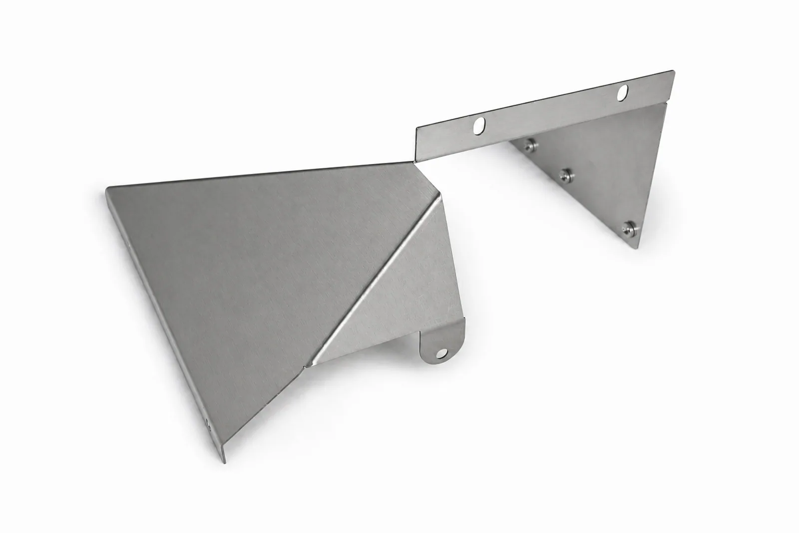
Typical tolerance references
Typical reference only. Final tolerance capability depends on material, thickness, bend count, tooling, feature location and drawing requirements.
Forming / cosmetic review
Press-brake forming is well suited to parts whose function depends on controlled flanges, channels, brackets, covers, trays and enclosure geometry without dedicated stamping dies for many prototype and repeat-production routes.
Create defined bend lines and repeatable formed geometry for brackets, panels, channels and structural sheet-metal parts.
Many formed geometries can be produced using standard press-brake tooling rather than dedicated stamping dies, subject to design and tooling review.
A reviewed bend sequence can often continue from design validation into repeat fabricated production as the part matures.
Bent parts can move into hardware insertion, welding, assembly and finishing within the same reviewed sheet-metal route.
Forming strategy depends on material, thickness, target radius, flange length, tooling access, bend sequence and the dimensions that control final fit.
Create single and repeated linear bends for brackets, covers, panels and structural sheet-metal components.
Form U-channels, Z-forms, trays, covers and enclosure geometry where tooling access remains practical.
Coordinate parts that require multiple bends, controlled sequence and cumulative dimensional review.
Review geometry that may require multiple orientations, specialized tooling, relief features or secondary operations.
Feature placement and flange geometry must preserve material support, limit deformation and leave a workable path for the selected tooling.
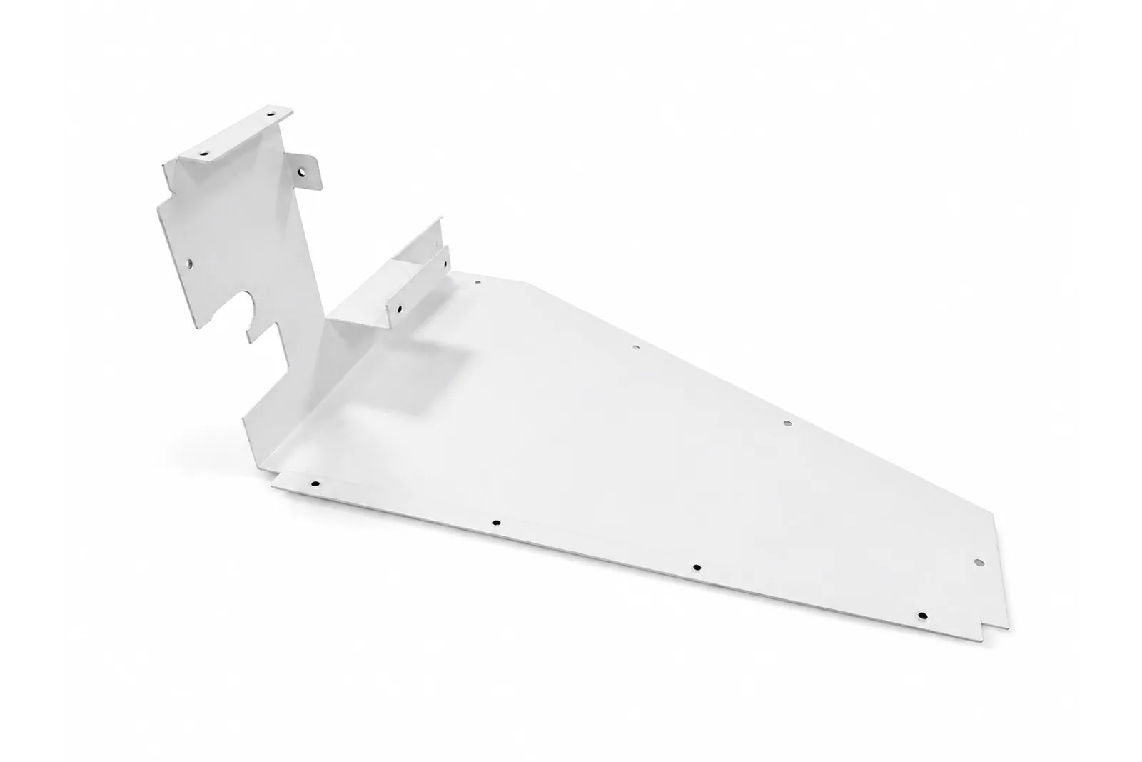
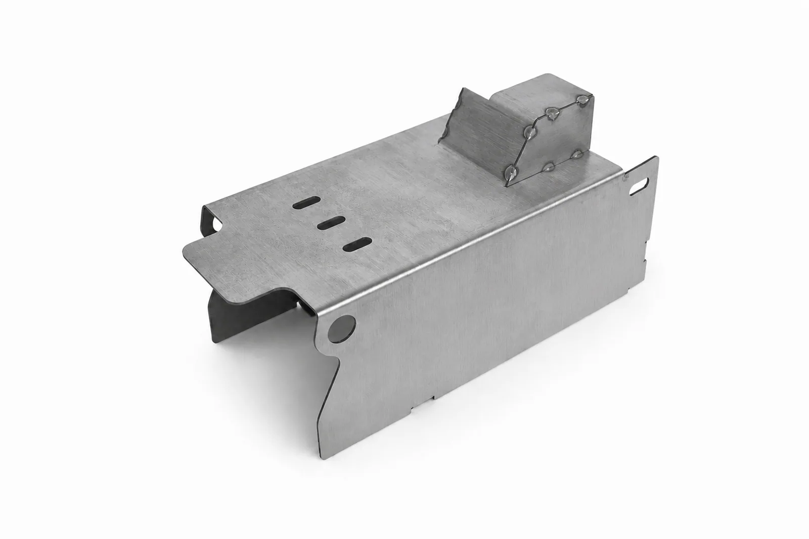
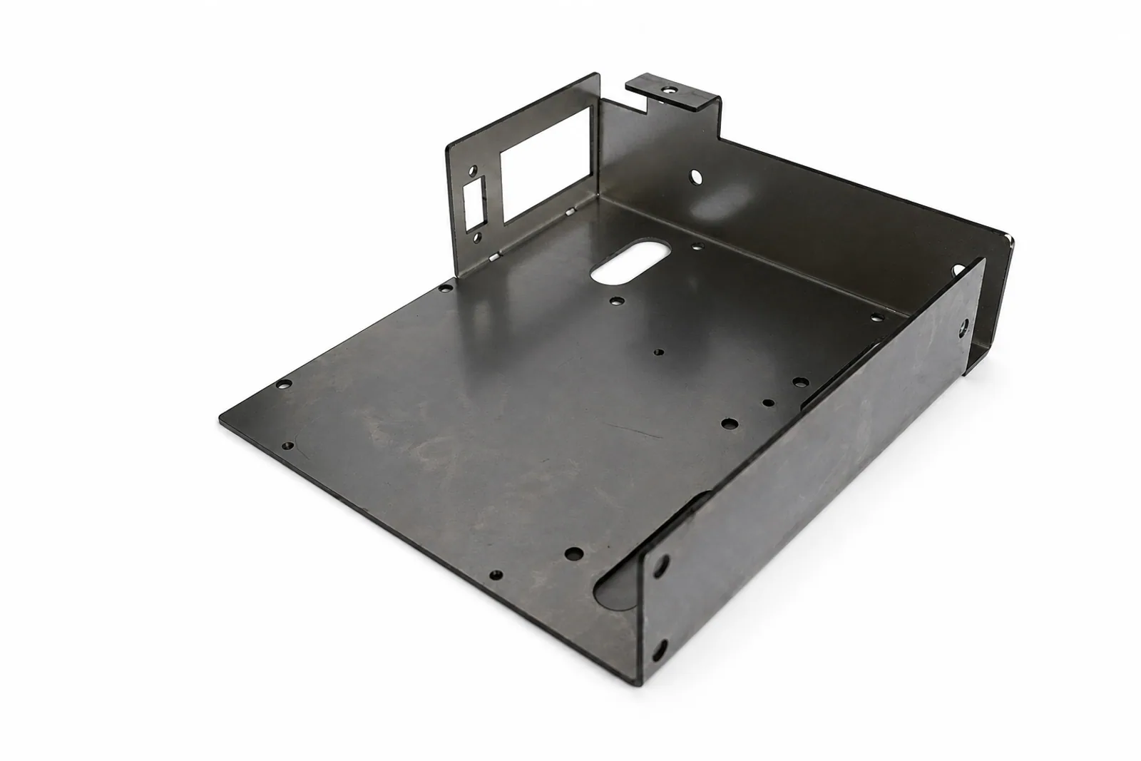
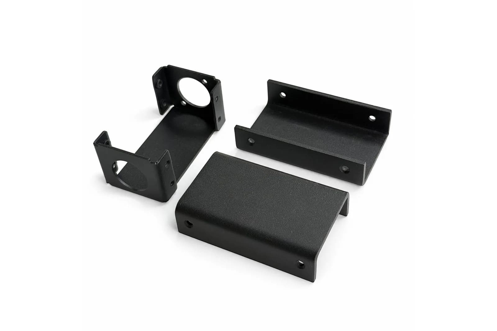
Material grade, temper, thickness, grain direction and selected bend radius all influence whether a part can be formed cleanly and consistently.
Grade examples
Common for lightweight brackets, panels and enclosure parts. Bend suitability depends strongly on alloy, temper, thickness and inside radius.
Grade examples
Suitable for corrosion-resistant formed components, with tooling force, springback and cosmetic requirements reviewed according to grade and thickness.
Grade examples
A practical route for brackets, chassis, panels and structural formed parts, with bend geometry and finish condition reviewed per project.
Grade availability
Reviewed for project-specific conductive, shielding, decorative or functional requirements because ductility and surface condition influence forming behavior.
Material grade, temper, thickness, grain direction and forming suitability are confirmed before quotation.
L-brackets, formed supports, mounting tabs and structural brackets.
U-channels, trays, rails and protective formed structures.
Bent covers, face panels, access panels and protective sheet-metal surfaces.
Equipment chassis and structural formed parts prepared for hardware or joining.
Side panels, covers and box-like forms used within complete fabricated enclosures.
Engineering builds used to validate fit, angle, access and assembly before repeat production.
Review material, thickness, bend lines, radii, flange geometry, critical dimensions and nearby features.
Confirm forming strategy around material behavior, target radius, die opening and tooling access.
Determine the forming order required to avoid tool collision and preserve access to later bends.
Create the approved bends according to the reviewed sequence and tooling route.
Add approved hardware, joining or finish operations after forming where required.
Review bend angle, formed dimensions and functional interfaces before shipment or the next assembly stage.
Clear formed and flat-pattern information helps engineering review the complete bending route rather than interpreting an isolated profile.
A sheet-metal-aware 3D model helps communicate bend direction, finished geometry and assembly intent.
Use a drawing to identify material, thickness, critical formed dimensions, bend angles, radii, cosmetic surfaces, hardware and inspection requirements.
If a flat pattern is supplied, bend lines and finished geometry must remain consistent with the intended formed part.
Conflicting flat and formed files, duplicate lines, open contours or unclear bend direction can delay engineering review.
Current RFQ upload formats
Sheet metal changes through the bend region. Successful forming therefore depends on radius, flange support, feature placement, bend relief and the way multiple bends interact.
Do not treat a bend as a perfectly sharp corner. Inside radius should be reviewed around material, thickness and tooling.
A press brake requires enough flat material to contact and support the part during forming. Very short or tapered flanges may distort or become impractical to form.
Holes, slots and cutouts near a bend line may stretch or deform as the material is formed.
Relief geometry can reduce tearing, bulging and corner interference where bends terminate or adjacent flanges meet.
The inside radius is a real formed geometry controlled by material behavior, thickness and the selected tooling route.
Tooling affects bend radius, required force, flange support and whether nearby features enter a deformation zone.
Harder or less ductile material conditions may require larger radii or different forming strategies.
After forming force is released, material can recover slightly toward its original shape. Springback varies by material, thickness, bend angle and forming method.
Radius and tooling recommendations are confirmed during engineering review; HERUIYUN does not apply one universal bend-radius rule to every material.
Material stretches on the outside of a bend and compresses on the inside. Flat-pattern compensation must account for the bend region before cut geometry is treated as final.
The developed length of the bend region along the neutral zone used when calculating the flat blank.
A compensation method used to relate finished flange dimensions back to the required flat length.
K-factor describes the approximate location of the neutral axis through the sheet thickness and is one input in flat-pattern calculation.
Actual compensation depends on material, thickness, radius, tooling and forming method and should be confirmed against the production route.
Flat-pattern compensation is confirmed according to the actual material and forming route.
The correct sequence depends on whether an operation can be completed before forming without distortion or must wait until final geometry is established.
Upload your CAD model or drawing for review of material, thickness, bend radius, flange geometry, nearby features, tooling access and downstream assembly requirements.