
Linear casting tolerance reference
| Feature size | Standard reference | Closer review |
|---|---|---|
| Up to 25 mm | ±0.10 mm | ±0.05 mm |
| >25–50 mm | ±0.15 mm | ±0.08 mm |
| >50–100 mm | ±0.20 mm | ±0.10 mm |
| >100–200 mm | ±0.30 mm | ±0.15 mm |
| >200–400 mm | ±0.40 mm | Project review |
01 / DIE CASTING
Production-focused high-pressure die casting for aluminum, zinc and magnesium parts—from DFM and tooling through casting, post-machining, finishing and repeat supply.
HERUIYUN reviews alloy, wall geometry, draft, ribs, bosses, gate and runner strategy, venting, machining allowances and critical inspection features before tooling is released.
Get Die Casting Quote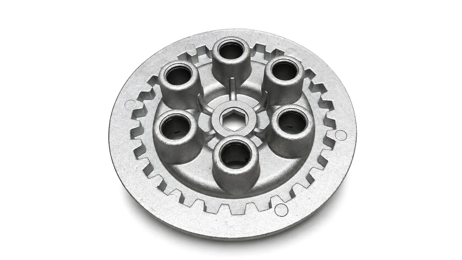
02 / ALLOY SELECTION
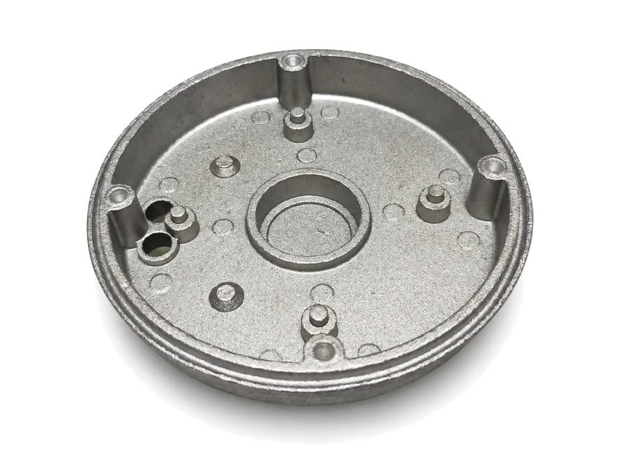
Select the alloy family around mechanical, thermal, weight, finish and production requirements. Listed grades are reference options; final availability and suitability are confirmed during engineering review.
ALLOY FAMILY
A practical route for lightweight structural parts, housings and heat-management geometry. Final alloy selection depends on strength, corrosion, thermal, finishing and dimensional requirements.
REPRESENTATIVE GRADES
ENGINEERING FOCUS
03 / DIE CASTING CAPABILITIES
Press selection, chamber route, vacuum assistance and secondary machining are planned as one manufacturing system—not isolated process labels.
A common route for aluminum and selected magnesium alloys where the molten metal is transferred into the shot chamber for each cycle.
A fast-cycle route commonly associated with zinc and compatible alloys, subject to part geometry, alloy and tooling review.
Vacuum assistance may support cavity evacuation and reduce trapped-gas risk. Vacuum levels up to 95% are process- and geometry-dependent, not a universal part guarantee.
Critical bores, faces, threads and datums can be machined after casting. Capability down to ±0.02 mm is feature-, datum- and inspection-dependent.
04 / PROJECT WORKFLOW
A compact release path keeps product geometry, tooling, T1 findings and repeat-production controls connected.
Review CAD, drawing, alloy, volume, critical features and finish requirements.
Define die construction, cavity, gate, runner, venting, ejection and process route.
Evaluate initial castings for fill, porosity risk, dimensions, appearance and assembly fit.
Control the approved casting, trimming, machining, finishing and inspection sequence.
05 / TOOLING STRATEGY
Tool material, cavity layout, feed system, side actions, thermal balance and maintenance determine whether a casting route can repeat reliably.
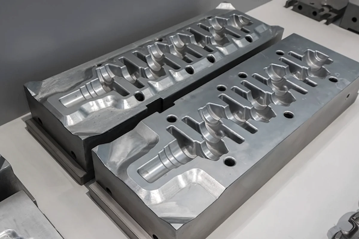
H13 is commonly reviewed for production tooling; NAK80 and other project-specific materials may be considered according to alloy, volume and tool strategy.
Single- or multi-cavity decisions depend on part size, press selection, projected demand, balance and quality risk.
The feed system is developed around fill direction, velocity, thermal behavior and trimming requirements.
Side actions can release undercuts but add tooling, timing and maintenance complexity.
Die-temperature control supports cycle stability, release and dimensional consistency.
Planned cleaning, wear review and revision control help preserve repeat-production continuity.
H13 tool steel hardened to approximately HRC 48–52 may be considered for suitable production dies. Material, hardness, heat treatment and tool-life expectation remain alloy-, geometry- and maintenance-dependent.
06 / DIE-CAST PARTS
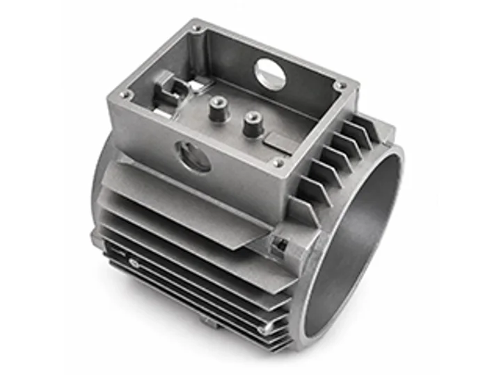
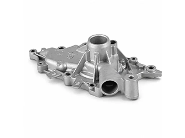
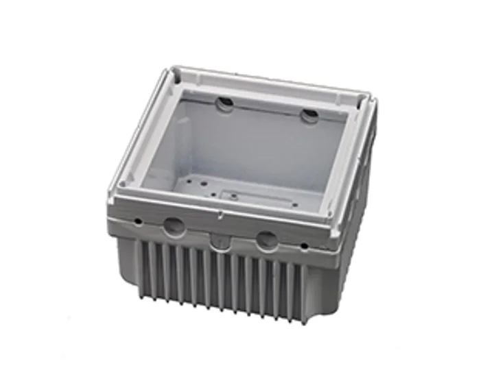
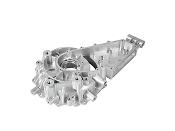
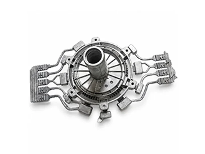
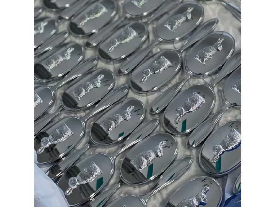
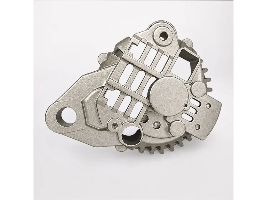
Representative real-source parts show fins, ribs, ports, frames and production batches. The gallery is process evidence, not an industry or certification claim.
07 / DESIGN FOR DIE CASTING
Die-casting DFM aligns geometry with metal flow, ejection, die construction and any critical machining that follows.
Keep wall distribution as consistent as practical. For A380, 2.0–3.5 mm is a useful starting reference; localized sections near 1.5 mm require geometry and process review.
Internal walls commonly need about 1°–1.5° draft as a starting reference. Depth, alloy, texture and ejection direction can require more.
Use ribs to support stiffness without creating unnecessary local mass, and connect bosses with controlled transitions.
Smooth section changes support metal flow, reduce stress concentration and improve die manufacturability.
Locate the parting line, ejector contact and trim evidence away from critical sealing or cosmetic zones where practical.
Reserve stock and define datums where bores, sealing faces or other critical interfaces will be CNC machined after casting.
08 / FLOW, VENTING & POROSITY
Gate, runner, overflow, venting and thermal behavior are reviewed together. The visual is a deterministic engineering schematic, not a simulated CFD result.
Controls how metal enters the cavity and influences flow direction, speed and local trimming evidence.
Provides planned destinations for initial flow and controlled paths for displaced air.
Die temperature, local mass and cooling influence fill, solidification, shrinkage and cycle stability.
Geometry, process settings, venting, vacuum assistance and downstream machining are reviewed together where internal quality matters.
Vacuum assistance up to 95% may be available in suitable process systems. It supports cavity evacuation but does not guarantee porosity-free castings.
09 / SECONDARY CNC MACHINING
Casting creates near-net geometry; CNC machining establishes selected precision interfaces; inspection closes the loop against the drawing.
Post-casting machining capability down to ±0.02 mm is feature-, datum-, setup- and inspection-dependent. Critical requirements must be identified on the drawing.
10 / SURFACE FINISHING
Finish selection starts with alloy chemistry, casting condition, pretreatment, masking and the required appearance or environment.
Trimmed and cleaned casting surface retained where functional requirements allow.
A uniform blasted texture may be used to clean and visually equalize compatible cast surfaces.
A durable colored coating option subject to pretreatment, masking and end-use requirements.
Liquid paint systems may be reviewed for color, appearance and environment-specific requirements.
Project-specific plating may be reviewed for compatible alloys and surface preparation requirements.
Applicable primarily to compatible aluminum castings; alloy chemistry and casting porosity can affect cosmetic consistency.
11 / DIMENSIONAL CAPABILITY
Use these values only as quotation-stage references. Final capability depends on alloy, geometry, size, datum structure, die condition, process route and whether the feature is cast or machined.
| Feature size | Standard reference | Closer review |
|---|---|---|
| Up to 25 mm | ±0.10 mm | ±0.05 mm |
| >25–50 mm | ±0.15 mm | ±0.08 mm |
| >50–100 mm | ±0.20 mm | ±0.10 mm |
| >100–200 mm | ±0.30 mm | ±0.15 mm |
| >200–400 mm | ±0.40 mm | Project review |
| Alloy family | Casting behavior | Dimensional review |
|---|---|---|
| Aluminum | Lightweight structural casting | Geometry, thermal balance and post-machining datums |
| Zinc | Detailed geometry and stable surface definition | Part size, wall distribution and ejector strategy |
| Magnesium | Low-density structural casting | Alloy, corrosion protection and distortion risk |
No table replaces a drawing review. Closer values are not automatic production guarantees and may require secondary machining or an adjusted datum and inspection strategy.
12 / REPEAT PRODUCTION
Repeat supply depends on preserving the approved tool, process window, downstream sequence and drawing-controlled inspection—not only keeping a mold on a shelf.
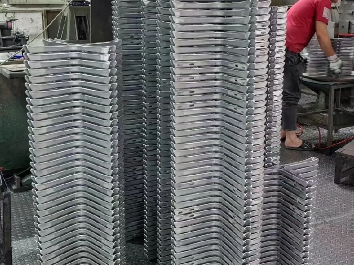
Expected life may range from 10,000 to 1M+ shots, depending on alloy, die material, geometry, maintenance and acceptance criteria.
Freeze the qualified casting, trimming, machining and finish sequence after engineering approval.
Track wear, cleaning, repair and replacement items against the approved tool revision.
Maintain project-defined production and inspection records for repeat orders.
Review CAD, drawing, alloy, finish or supplier-process changes before release.
Use the controlled tool, process plan and inspection criteria as the repeat-production reference.
13 / QUALITY CONTROL
The quality plan should follow the actual part risks: casting condition, critical geometry, post-machined features, surface treatment and final assembly interfaces.
Review fill, trim, flash, visible defects and process stability against the approved route.
Inspect drawing-defined dimensions, datums and post-machined interfaces with suitable equipment.
Confirm visible finish, coating, hardware and mating behavior where specified.
14 / PREPARE YOUR PROJECT
The more clearly the product, volume, alloy and critical interfaces are defined, the more directly tooling and process risk can be reviewed.
Provide the latest solid model for casting and tooling review.
Identify datums, critical dimensions, tolerances and inspection requirements.
Specify the required alloy or the mechanical, thermal and finish requirements for selection support.
Provide initial demand and expected repeat volume for press, cavity and tool-life planning.
Define visible zones, texture, coating, color and masking requirements.
Identify bores, faces, threads and datums that require CNC machining after casting.
Mark sealing, assembly and alignment features that control product function.
Share corrosion, temperature, load or conductivity requirements relevant to alloy and finish selection.
Define required reports, gauges and drawing characteristics before production release.
Upload your CAD and drawing for review of alloy, wall geometry, tooling, gate and venting strategy, post-machining, finish, quantity and critical dimensions.