Tool Access
- Risk
- Hardware or joining locations become unreachable after adjacent panels are installed.
- Review direction
- Preserve installation clearance or revise the sequence and fastener direction.

Build custom housings, chassis, control enclosures and multi-part sheet-metal assemblies with coordinated hardware, joining, finishing and final fit review.
HERUIYUN reviews panel geometry, bends, hardware, service access, assembly sequence, cosmetic surfaces and final installation requirements before confirming the enclosure manufacturing route.
Get an Enclosure Quote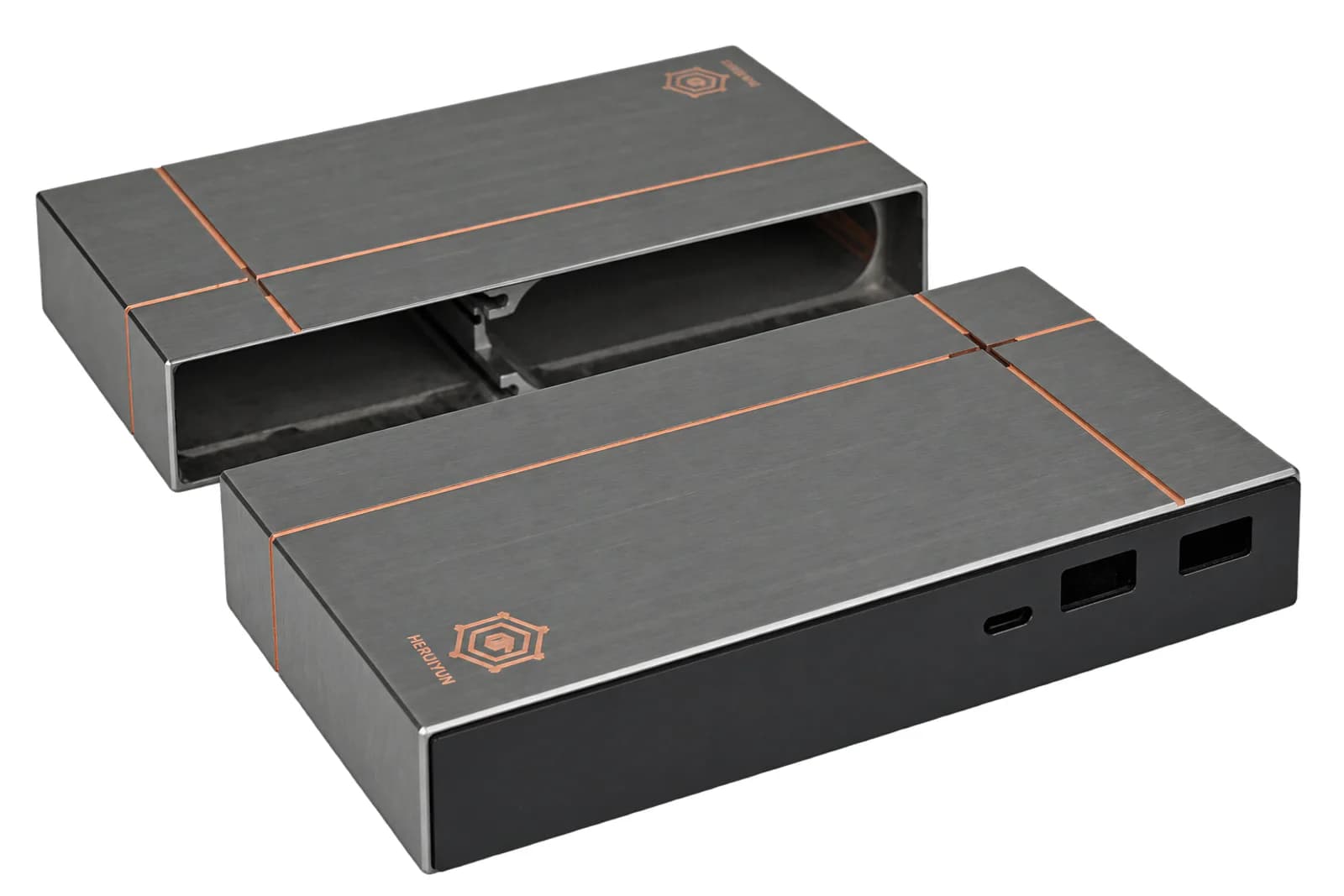
A functional enclosure combines formed panels, openings, hardware, joining, surface requirements and installation interfaces that must be reviewed as one assembly rather than as unrelated parts.
Protective housings, covers and equipment shells designed around access, mounting and final-use requirements.
Structural chassis, mounting bases and internal frames prepared for hardware, subassemblies or installed equipment.
Front, rear, access and interface panels with reviewed openings, fastener strategy and serviceability.
Assemblies combining formed panels, brackets, hardware, rivets or welded joints into a finished enclosure structure.
Panel holes, bends, brackets, hardware and cover interfaces can be reviewed together instead of allowing independent part tolerances to accumulate unnoticed.
A project can be evaluated around the actual assembly sequence so that individually acceptable parts still fit together as intended.
Hardware insertion, masking, coating, joining and final assembly can require a specific operation order that should be planned before production.
An enclosure can be validated as a complete assembly before repeat production, preserving the reviewed interface and hardware strategy.
Thin sheet often requires dedicated hardware for reliable threads, spacing, removable covers and subassembly mounting. Hardware type, edge distance, installation direction and finishing sequence should be reviewed before release.
Provide threaded attachment points in suitable sheet thicknesses without relying on a tapped sheet edge alone.
Create controlled spacing for internal panels, boards or mounted subassemblies where the project requires it.
Support locating, mounting and component retention without requiring a loose fastener on both sides.
Support removable covers, permanent panel joints or serviceable enclosure interfaces depending on the selected hardware route.
Hardware family, exact part number, material, sheet-thickness compatibility and installation sequence are confirmed during engineering review.
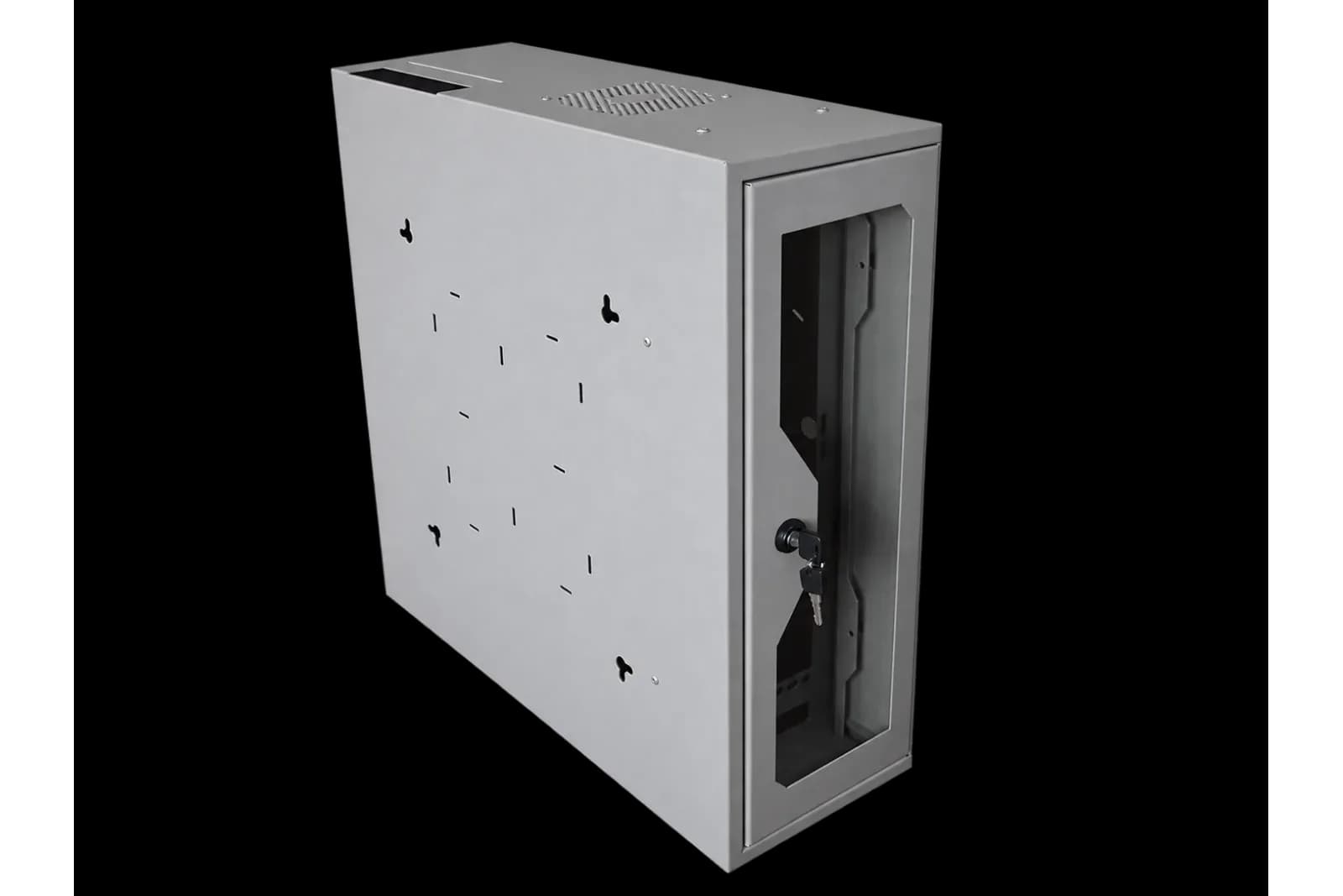
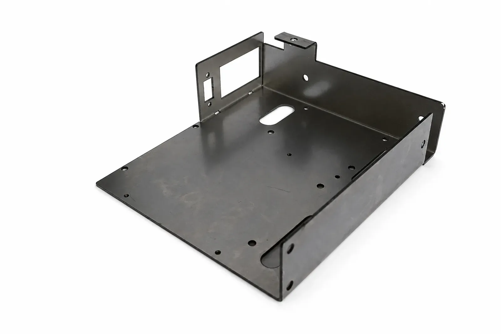
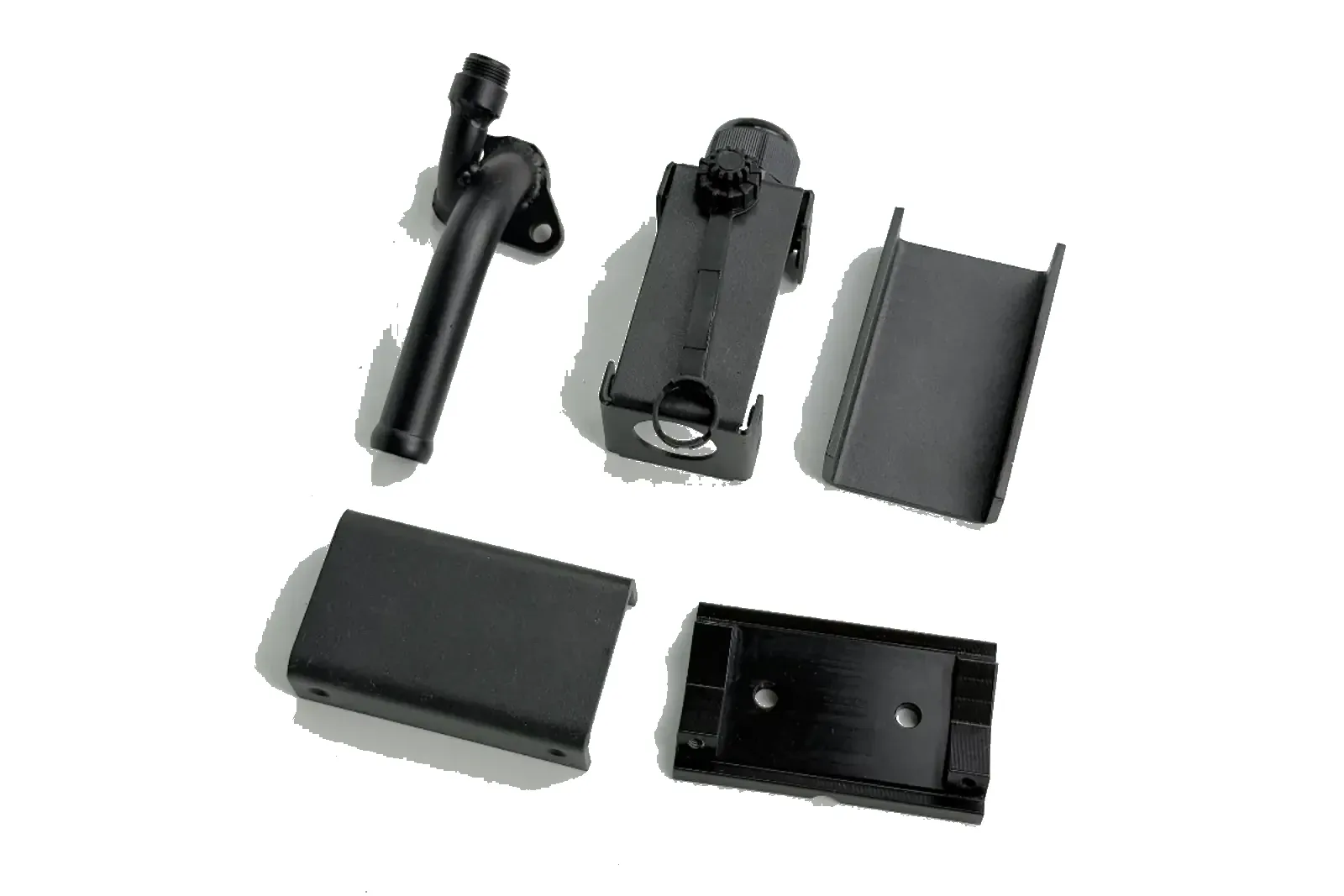
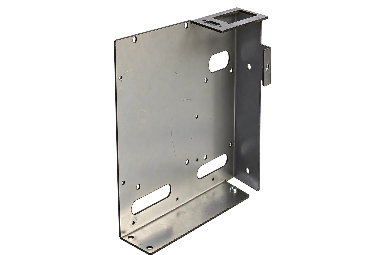
An enclosure can be dimensionally correct and still be difficult to assemble or maintain. Tool access, fastener direction, removable panels and assembly order should be reviewed before hardware and finish lock the design in place.
A permanent joining route for structures where joint access, heat input and post-weld finishing have been reviewed.
A low-heat mechanical route for suitable panel-to-panel joints and permanent assembled structures.
Provides integrated threads, studs or spacing features in compatible sheet geometry.
Supports removable panels, maintenance access and replaceable components where serviceability matters.
The final assembly method is selected around material, structural intent, access, appearance, production sequence and maintenance requirements.
Grade examples
Useful where lower weight, corrosion resistance and clean enclosure geometry are important. Forming and finishing suitability depend on alloy, temper and thickness.
Grade examples
Suitable for corrosion-resistant housings, chassis and panels where durability or visible metallic surfaces matter.
Grade examples
A practical route for structural chassis and equipment enclosures, often paired with protective coating or paint.
Availability
Reviewed where zinc-coated material is suitable for the application and compatible with the selected joining and finishing sequence.
Availability
May be reviewed for conductive, shielding, decorative or specialty panel requirements.
Material grade, temper, thickness, surface condition and availability are confirmed before quotation.
An enclosure is defined as much by its openings and interfaces as by its outer shape. Ventilation, connectors, cable entry, mounting patterns and service access should be coordinated with bend geometry and hardware.
Slots, perforations and airflow openings should be reviewed around strength, bend regions and final internal layout.
Panel openings for connectors, glands or cable entry should include sufficient edge distance, installation access and labeling space.
Hole and slot patterns for internal or external mounting should be reviewed around hardware, datum strategy and assembly fit.
Displays, switches, access ports and removable interface panels require coordinated cut geometry and final-use access.
Where electrical bonding is required, the intended metal-to-metal contact area should be identified on the drawing.
Powder coat or other insulating finish may need to be excluded from defined contact or grounding zones.
Hardware insertion, joining, masking and finishing may require a specific operation order to protect fit and functionality.
Fasteners, conductive interfaces and cosmetic surfaces should be reviewed together so finishing does not interfere with installation or contact.
Grounding, EMI, shielding or electrical-performance requirements are project-specific and require defined customer criteria. Standard enclosure fabrication does not imply certification.
An enclosure combines cut-feature location, bend variation, hardware placement, joined-part movement and finish thickness. Final fit should therefore be reviewed at assembly level rather than only part by part.
Adjacent panels, overlaps and mating edges should be reviewed around the dimensions that control final alignment.
Removable covers and doors require adequate gap, fastening strategy and repeatable interface geometry.
Inserted hardware can shift the effective assembly interface if location and installation direction are not controlled.
External mounting points, equipment interfaces and internal datum features should be prioritized during drawing and inspection review.
Final enclosure tolerance capability is confirmed according to material, bend count, joining route, hardware, finish and critical assembly requirements.
Review top-level assembly intent, individual parts, material, hardware, access and critical fit requirements.
Confirm cut geometry, bend lines, openings and part relationships before fabrication.
Produce the approved panels, brackets and chassis components through the reviewed laser-cutting and forming routes.
Install approved hardware and complete riveting, welding or mechanical joining in the required assembly sequence.
Coordinate masking, coating, anodizing, brushing, marking or other approved surface operations.
Review critical enclosure dimensions, hardware seating, panel alignment, cover fit and cosmetic requirements before shipment.
Provide the finished assembly model showing how panels, brackets, covers and hardware relate to one another.
Provide individual sheet-metal part geometry for cutting, forming and detailed manufacturing review.
Identify critical dimensions, datums, materials, finishes, hardware locations, cosmetic zones, masking and inspection requirements.
Provide exact hardware type, manufacturer part number or customer-approved equivalent requirement where specific fasteners, standoffs or panel hardware are required.
Inspection scope follows the drawing and assembly requirements rather than assuming one universal inspection plan for every enclosure.
Practical guidance for files, hardware, finishing, service access, tolerance stack-up and project-specific environmental requirements.
Upload your assembly CAD and drawings for review of panels, bends, hardware, joining, finish, service access and final-fit requirements.