
Anodizing
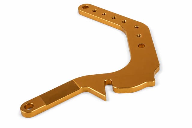
Color and conversion-finish references for machined metal components.
LOW-VOLUME MANUFACTURING
Pilot Runs, Bridge Production & Repeat Small-Batch Manufacturing
Move from validated prototypes to pilot runs and repeat small-batch production with manufacturing routes selected around part geometry, material, quantity, tolerance and finishing requirements.
Get a Quote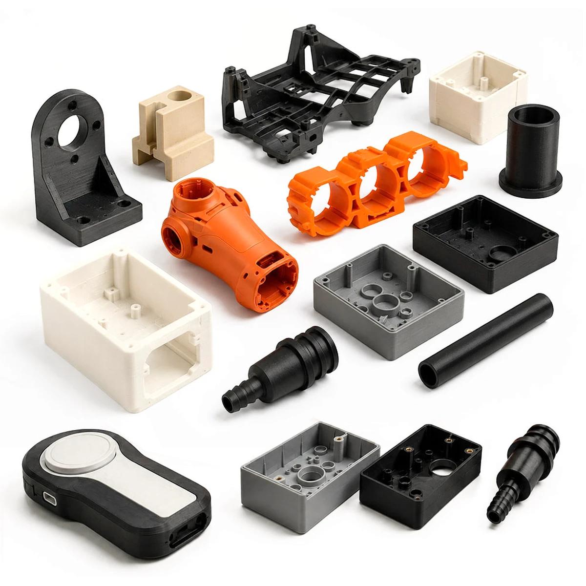
WHEN TO USE LOW-VOLUME
Low-volume manufacturing is useful when a design has moved beyond early prototyping but full-scale production is not yet the right manufacturing decision.
Produce initial functional batches to review manufacturing, assembly and final-part requirements before a larger production commitment.
Maintain part supply between prototype approval and the point where final production tooling or a higher-volume manufacturing route is ready.
Produce controlled initial quantities while actual product demand and downstream requirements become clearer.
Continue controlled engineering changes without committing the project too early to a manufacturing route that is difficult or expensive to revise.
Support projects that contain multiple part numbers, variants or component types in relatively small quantities.
Manufacture limited quantities for custom equipment, maintenance, replacement or specialized applications when large production runs are unnecessary.
PRODUCTION TRANSITION
Low-volume manufacturing creates a controlled transition between design validation and a more mature production strategy.
Review geometry, form, fit and early functional requirements before the manufacturing route is finalized.
Use initial batches to review part quality, assembly behavior and practical manufacturing requirements.
Continue supplying usable parts while demand, tooling or the final production strategy develops.
Repeat established manufacturing routes while checking current drawings, quantities and finishing requirements.
Reassess tooling and manufacturing strategy when repeat demand supports a different production route.
Review appearance and functional surface requirements against real product references and the selected manufacturing route.
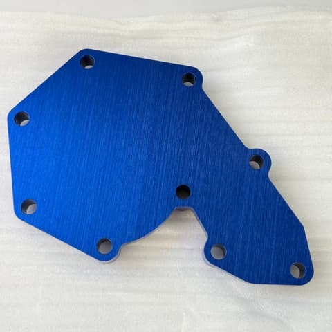
Color and conversion-finish references for machined metal components.
Painted prototype surfaces for color and appearance review.
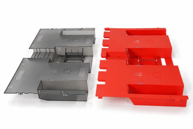
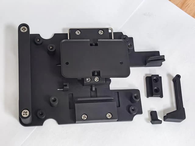
Coated fabricated parts with protective and cosmetic surfaces.
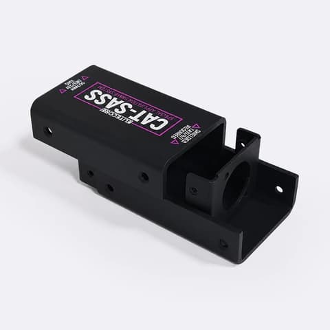
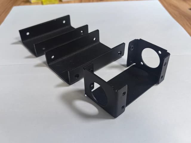
Matte blast-finish references; the blast medium is confirmed per project.
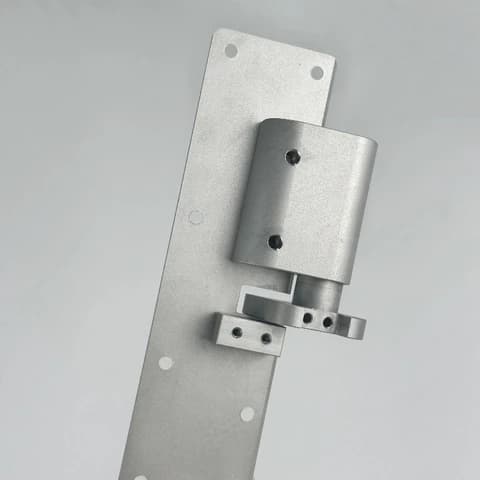
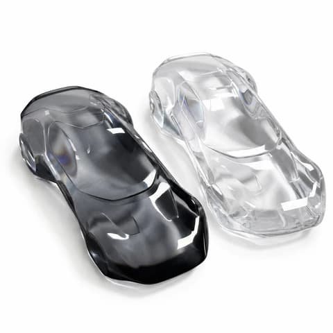
Reflective metal and clear acrylic surface references.
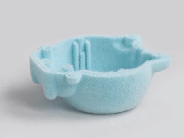
Directional brushing and flocked surfaces show distinct texture options.
PART READINESS
Low-volume production often requires more than base geometry. Finishing, appearance, marking and assembly requirements should be considered when selecting the manufacturing route.
Prepare edges and surfaces for handling, finishing or downstream operations where required.
Select project-specific finishing based on material, appearance, protection and functional requirements.
Define visible surfaces, color, texture and marking requirements where they are important to the final part.
Consider inserts, fitted components and assembly requirements before the production route is finalized.
MANUFACTURING REFERENCES
Explore documented materials, process routes and part geometries. These manufacturing references do not establish a particular order quantity or production batch.
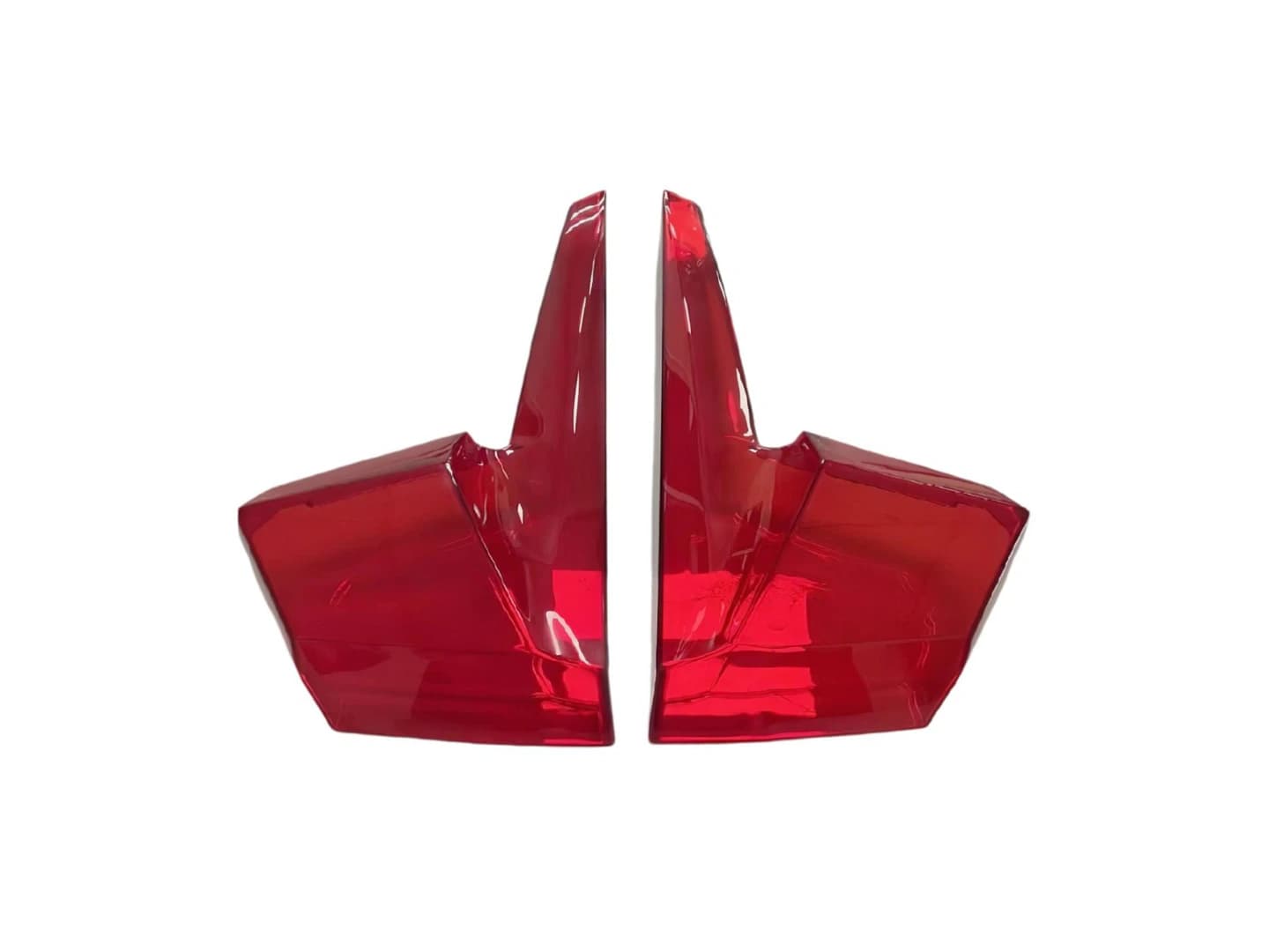
Transparent PMMA tail-light prototypes combine freeform surfaces with thin edges. CNC milling, progressive polishing and coloring support appearance and light-transmission review during automotive development.
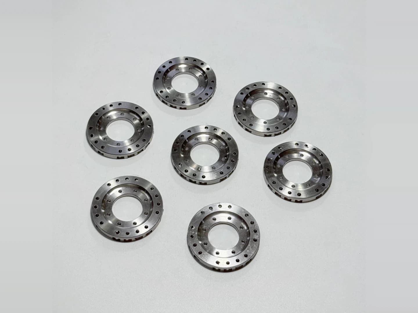
These precision turned parts combine stepped bores, concentric faces and circumferential mounting holes. The documented route uses turning followed by secondary drilling and milling for assembly interfaces.
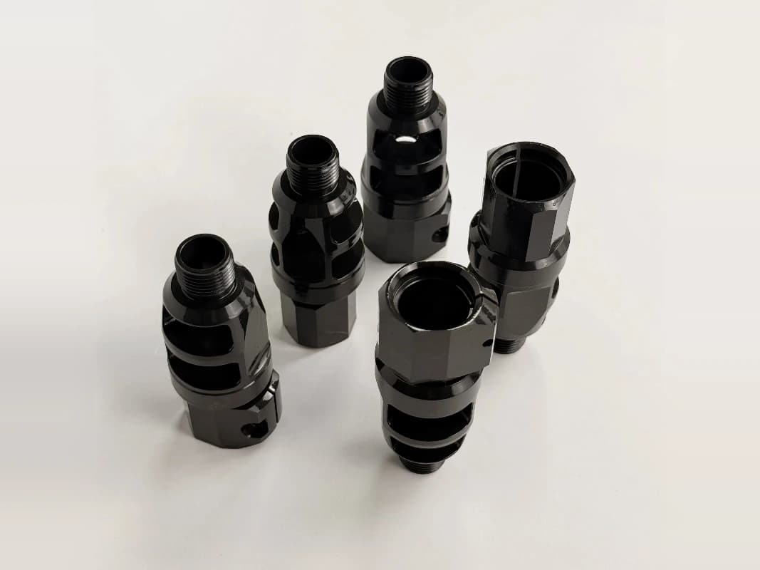
Turned cylindrical bodies combine threaded ends, side windows and hexagonal features. Milling and EDM produce secondary geometry before the documented QPQ treatment for equipment assembly.
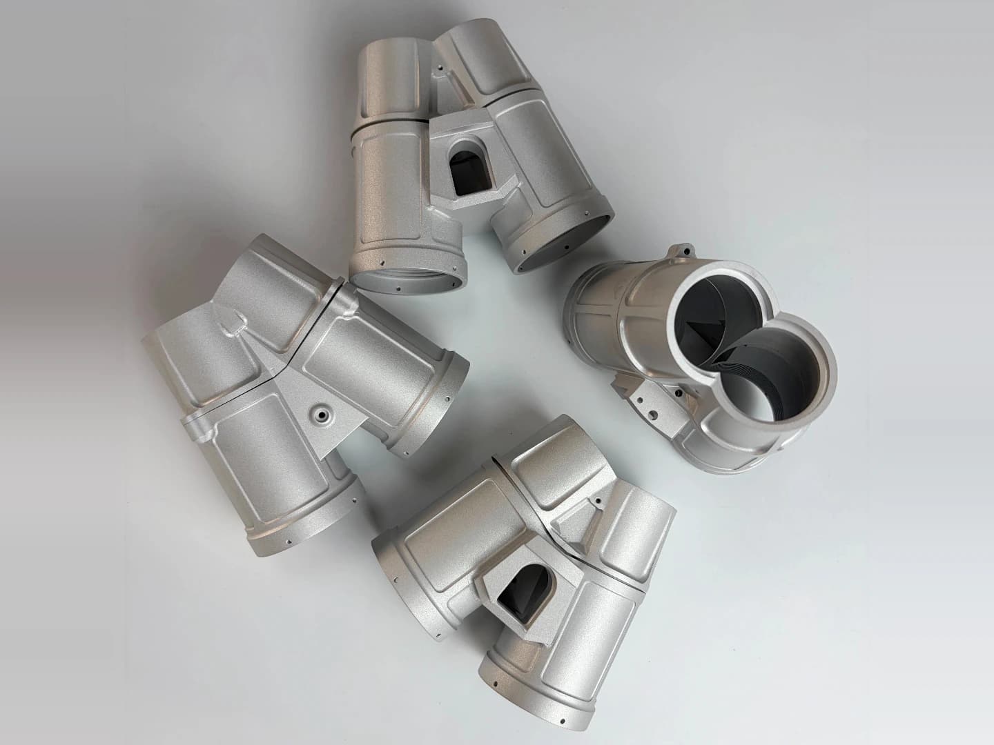
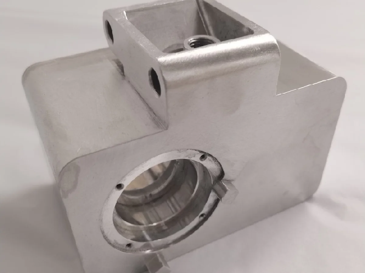
Five-axis CNC milling produces hollow housings with multiple mounting interfaces. The documented project used manufacturability review and dimensional inspection to resolve assembly interference before prototype testing.
07 / PRODUCT REFERENCES
Geometry references for low volume CNC machining and custom-part review. These photographs do not establish material grades, actual manufacturing routes or completed small-batch orders.
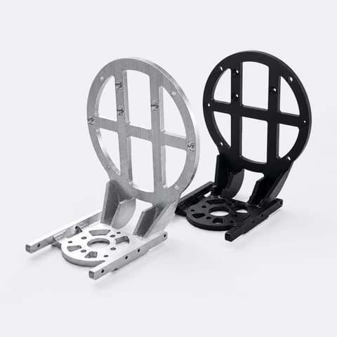
Reference geometries for custom precision machined parts, including locating faces, mounting interfaces and contoured profiles.
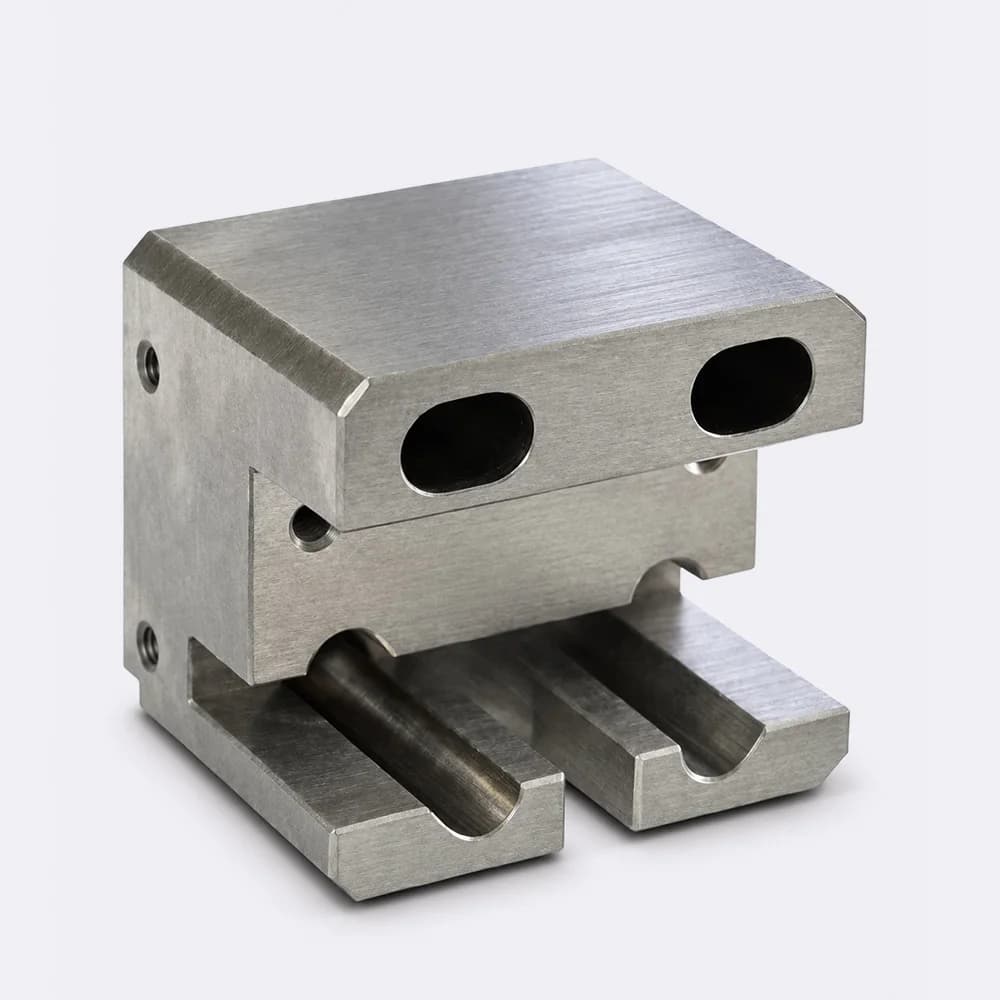
Two parallel bores sit above stepped lower channels, with side holes and broad flat mounting faces.
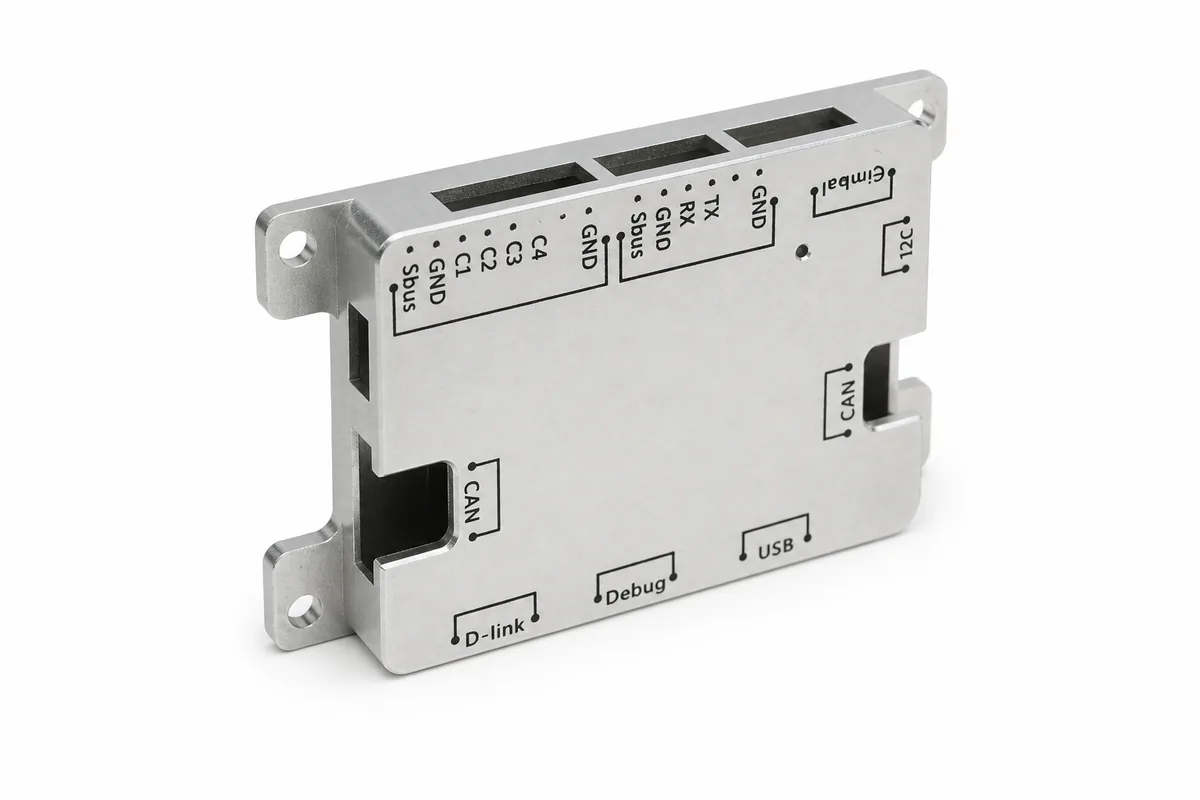
A flat interface plate carries recessed openings, perimeter mounting tabs and identification markings beside the connection areas.
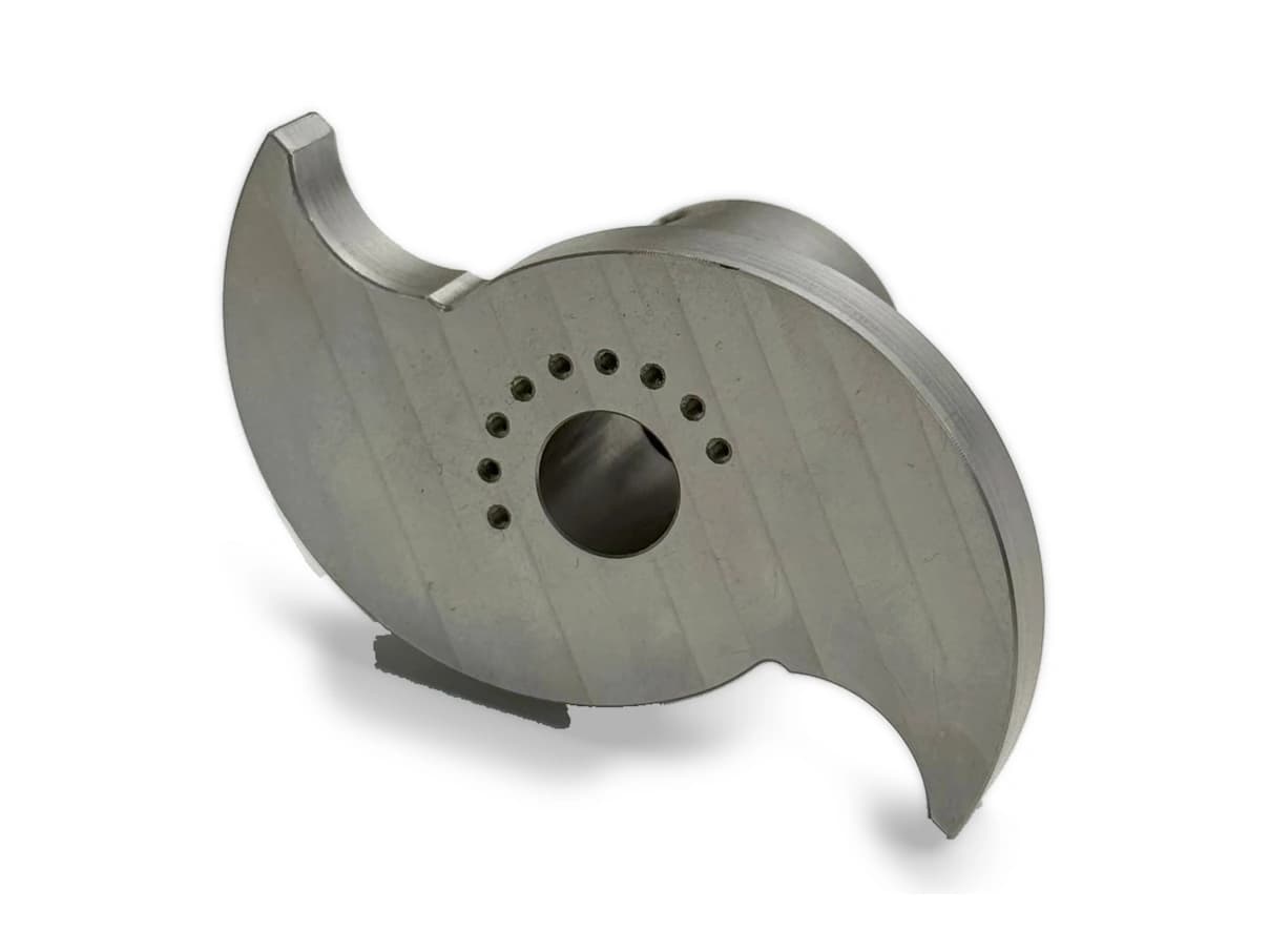
Two curved outer lobes surround a central bore and a short arc of smaller face holes.
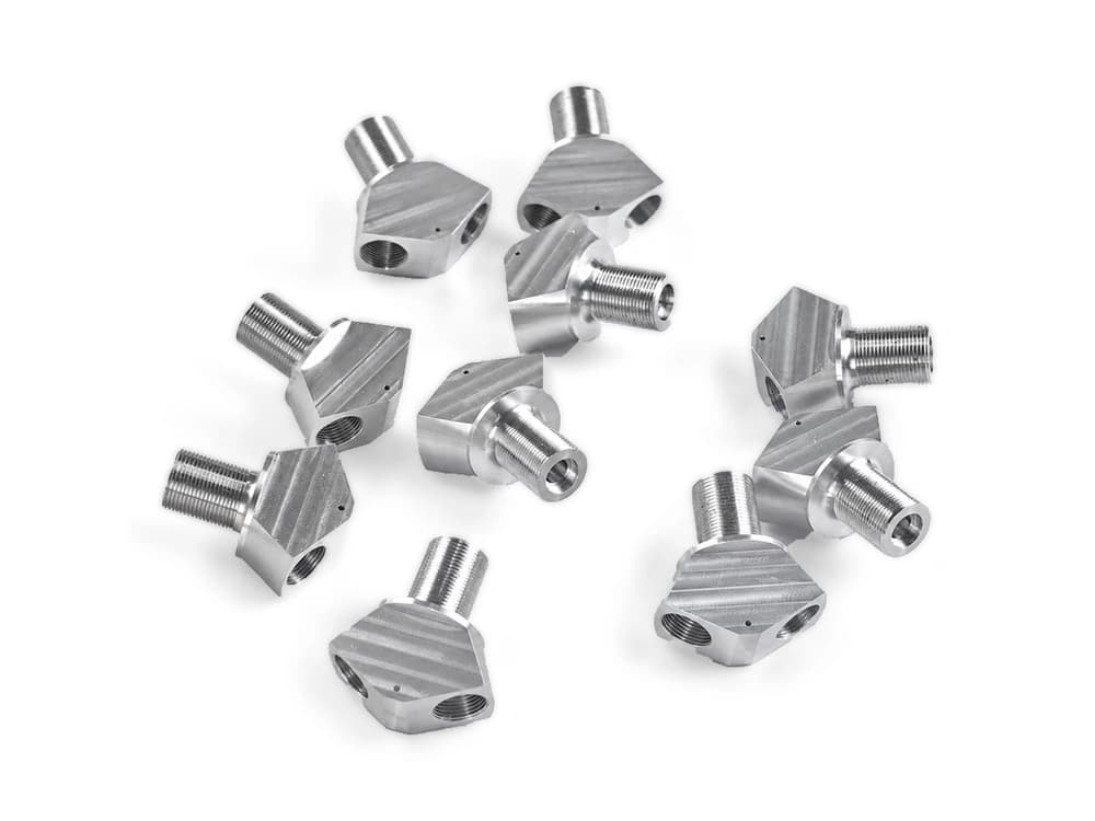
Compact connectors combine projecting cylindrical stems, shaped mounting faces and repeated small holes across separate pieces.
Review CNC machined enclosures around pocket access, wall transitions and mounting geometry; the actual route requires drawing confirmation.
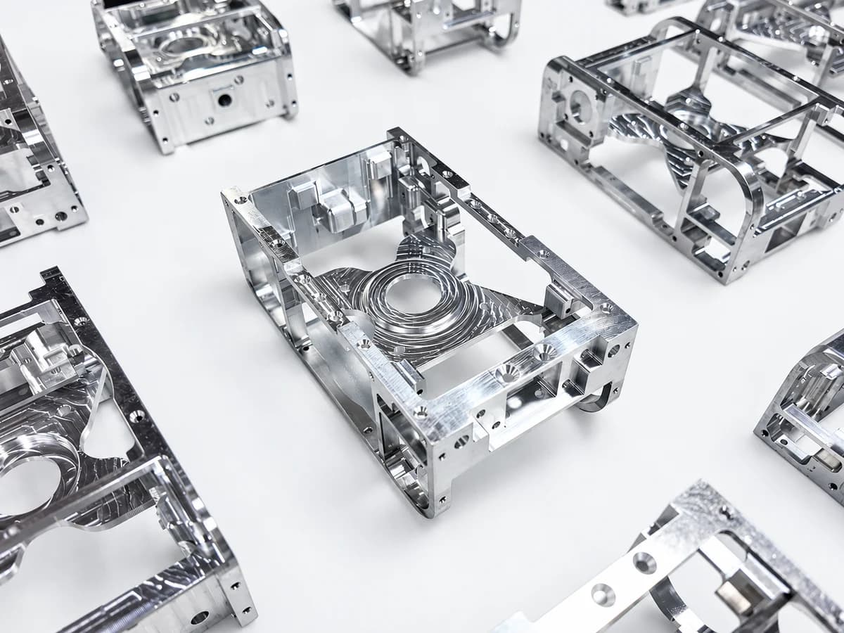
Open rectangular frames contain stepped pockets, circular bores and distributed mounting features across their inner and outer faces.
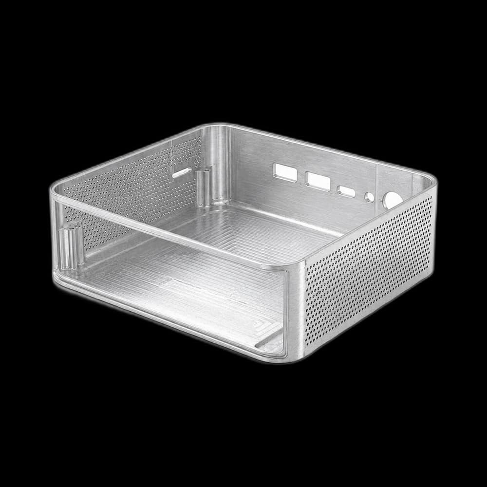
An open rectangular housing has ribbed sidewalls, a recessed base and small apertures along its mounting edges.
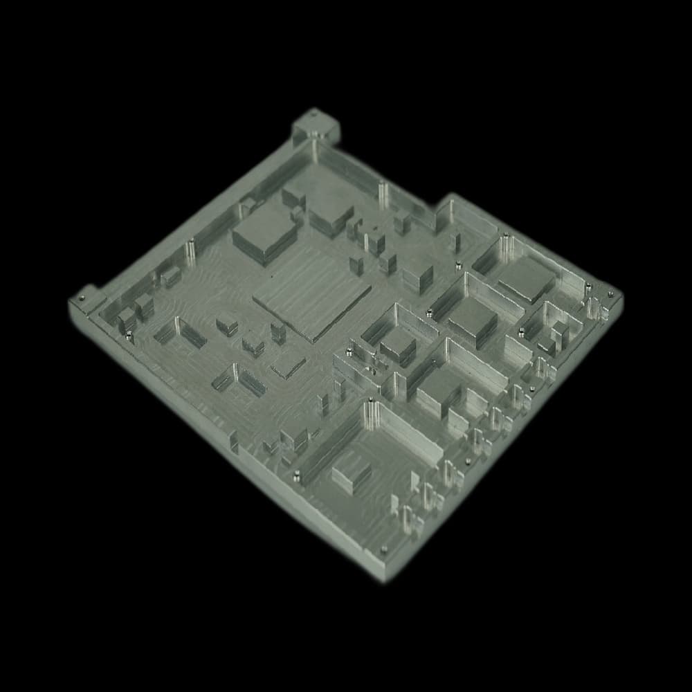
A shallow housing base contains several compartments, raised internal features and a continuous outer rim.
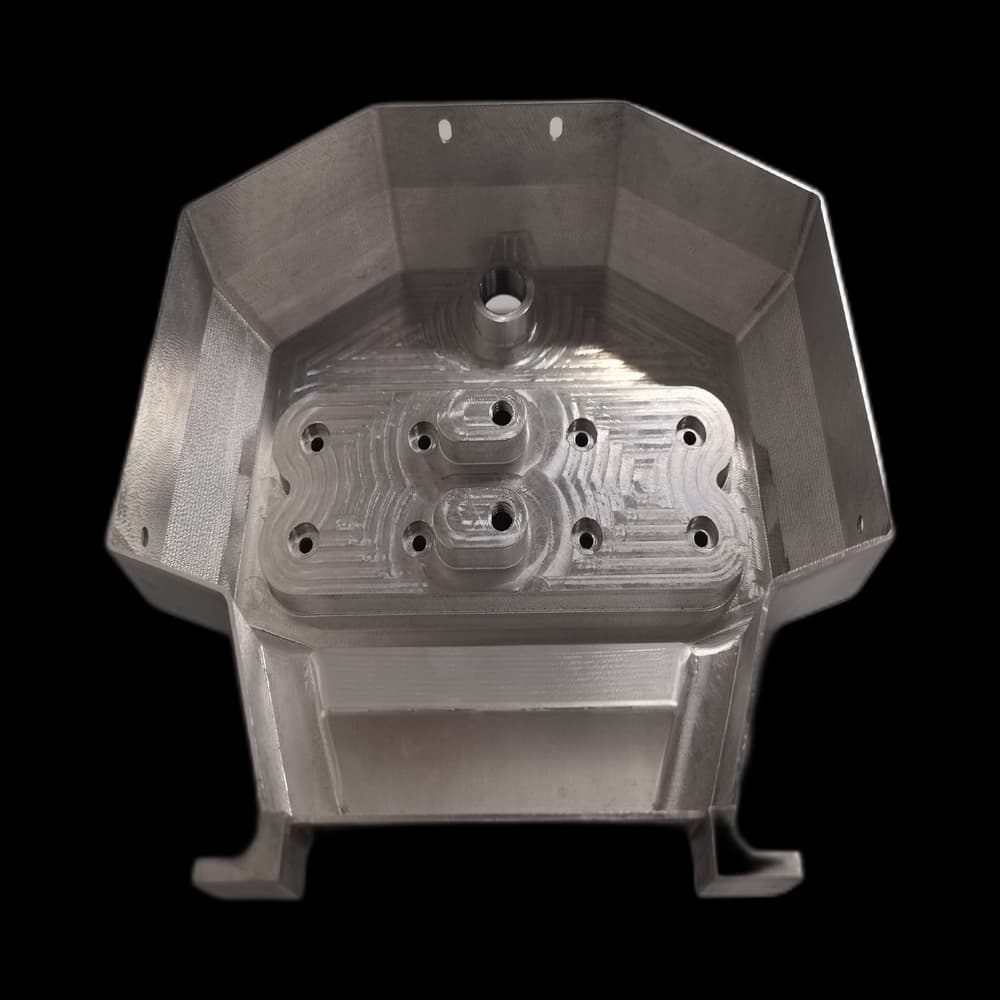
An angular housing surrounds a deep recess, stepped internal faces and a repeated pattern of smaller holes.
Rotational geometry references for small batch CNC parts, with stepped diameters, bores and mating faces reviewed individually.
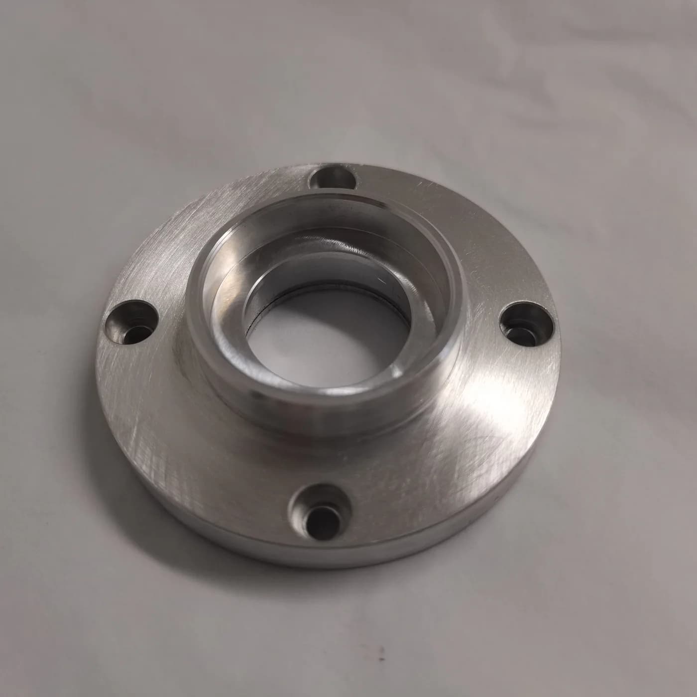
A circular flange presents a raised central collar, stepped inner bore and four evenly spaced face holes.
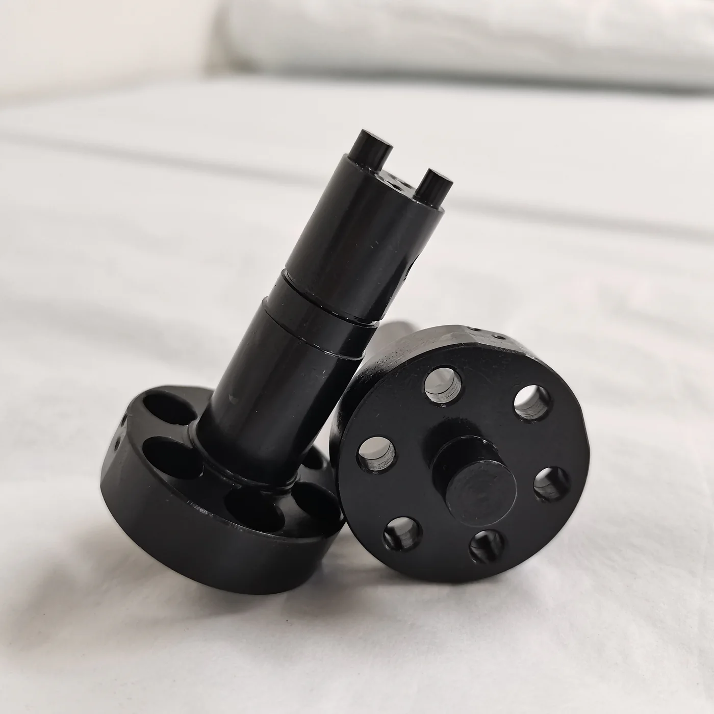
A long cylindrical shaft joins a broad flange beside a separate circular interface plate with a central opening.
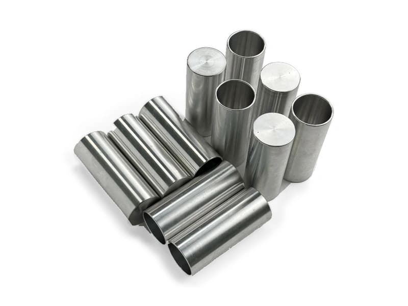
Several open-ended cylindrical sleeves show different lengths and diameters, with complete outer walls and visible internal bores.
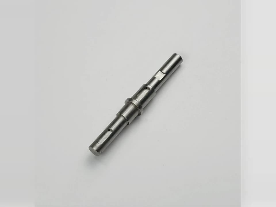
A slender shaft combines several diameter changes, shoulder transitions and a visible longitudinal recess near its end.
Locating and workholding references for fixture planning and inspection fixtures, without assuming a particular inspection capability.
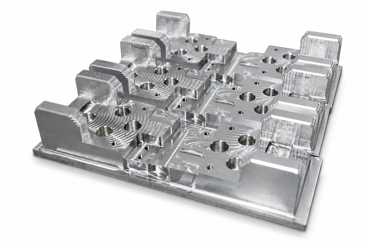
A broad plate combines raised locating blocks, distributed bores and closely spaced pockets across its working face.
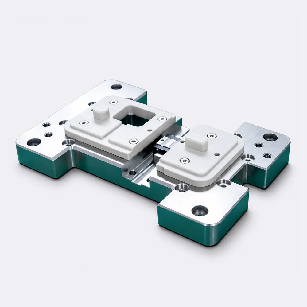
Two flat fixture assemblies contain locating blocks, fasteners and replaceable contact pieces arranged on shaped bases.
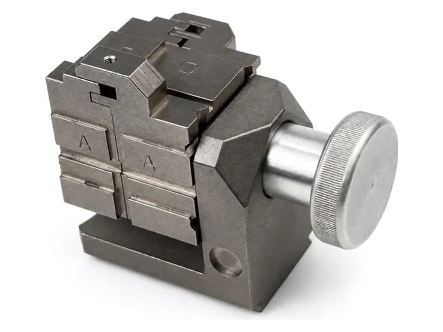
Opposed jaws, a screw-driven adjustment and flat supporting faces define this compact workholding assembly.
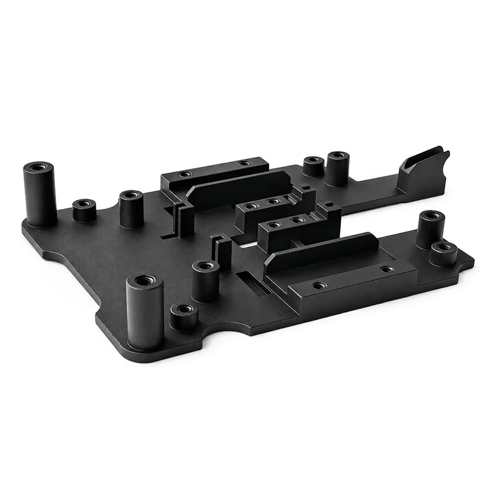
Two fixture bases combine upright bosses, paired locating rails and rectangular recesses around their mounting features.
Cross-port and tubular-junction geometry for reviewing custom manifolds and connector interfaces; internal flow paths and operating function need confirmation.
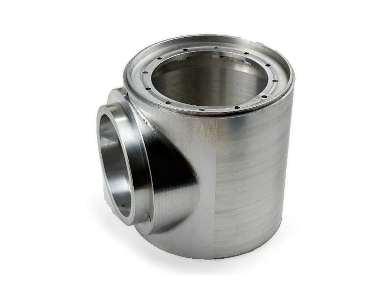
A cylindrical body has a large axial opening, a perpendicular side connection and small holes around the upper face.
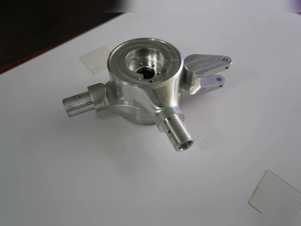
A circular central opening connects visually to projecting side interfaces, with mounting ears around the body.
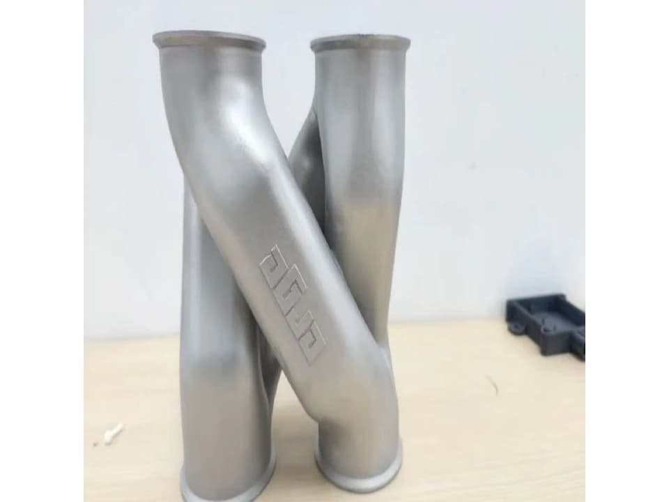
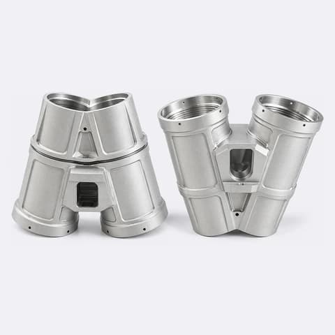
Two upright tubular openings meet a diagonal branch in this junction-shaped component; internal passage continuity and working function are unverified.
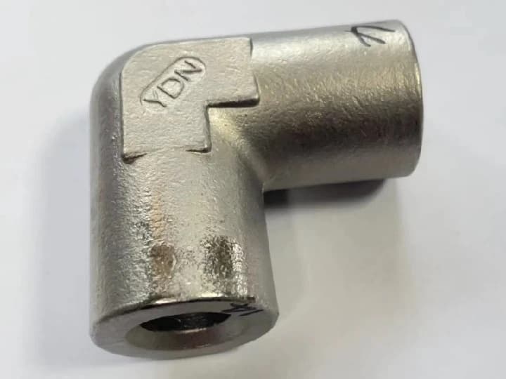
A right-angle body connects two cylindrical ends, with a visible open bore and stepped outer transitions; operating function is unverified.
Fins, ribs and contact-face geometry for thermal management components; photographs do not establish heat-transfer performance.
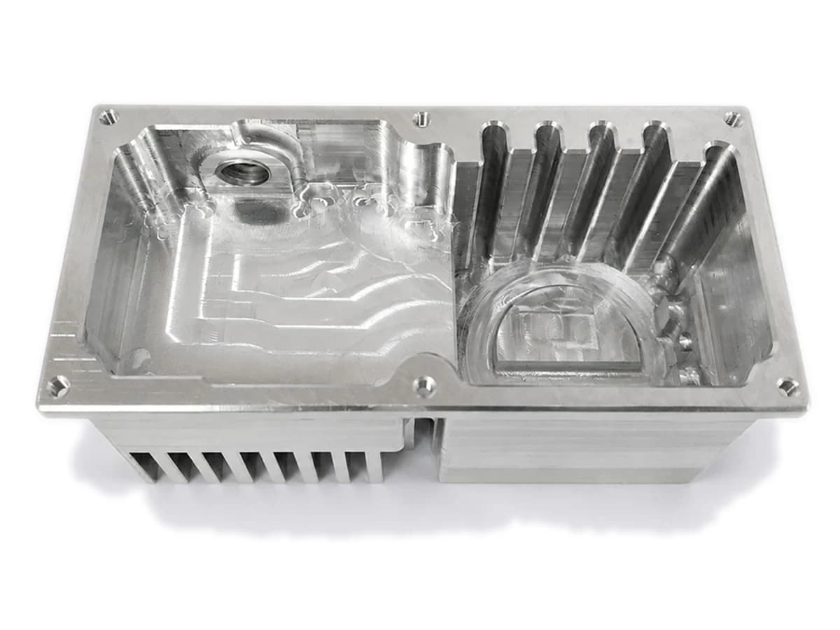
A recessed housing combines internal channels, upright ribs, a circular pocket and external fin-like features.
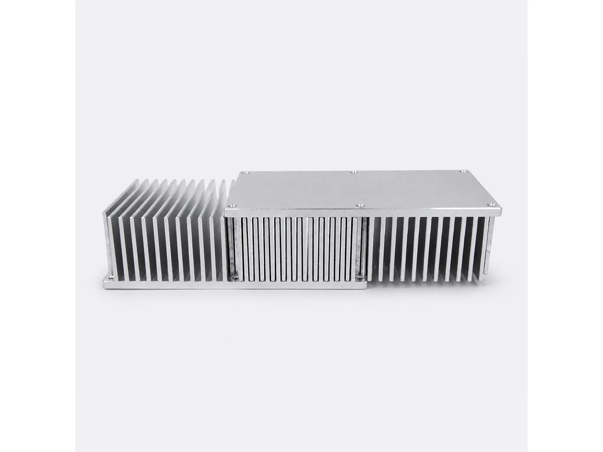
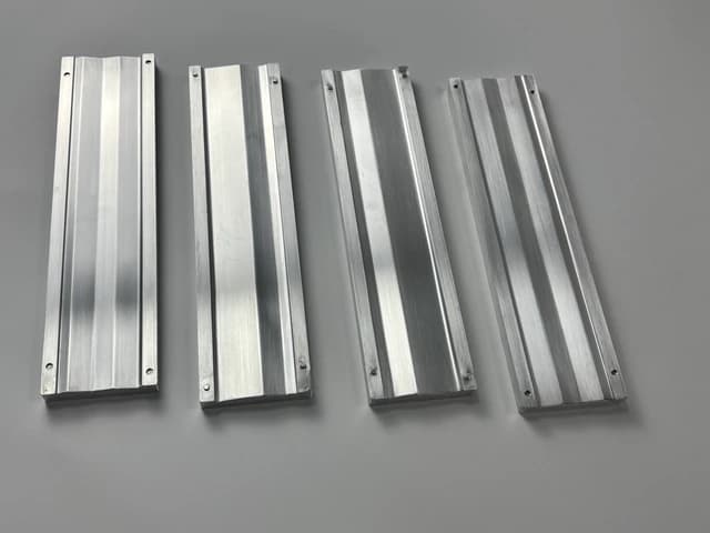
Dense parallel fins extend from a shared base, with taller end sections framing the repeated open spaces.
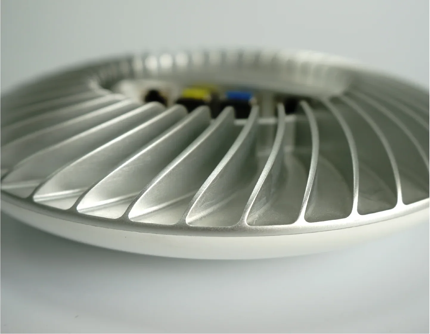
Curved fins spread around a central opening in a circular housing, leaving repeated gaps between the ribs.
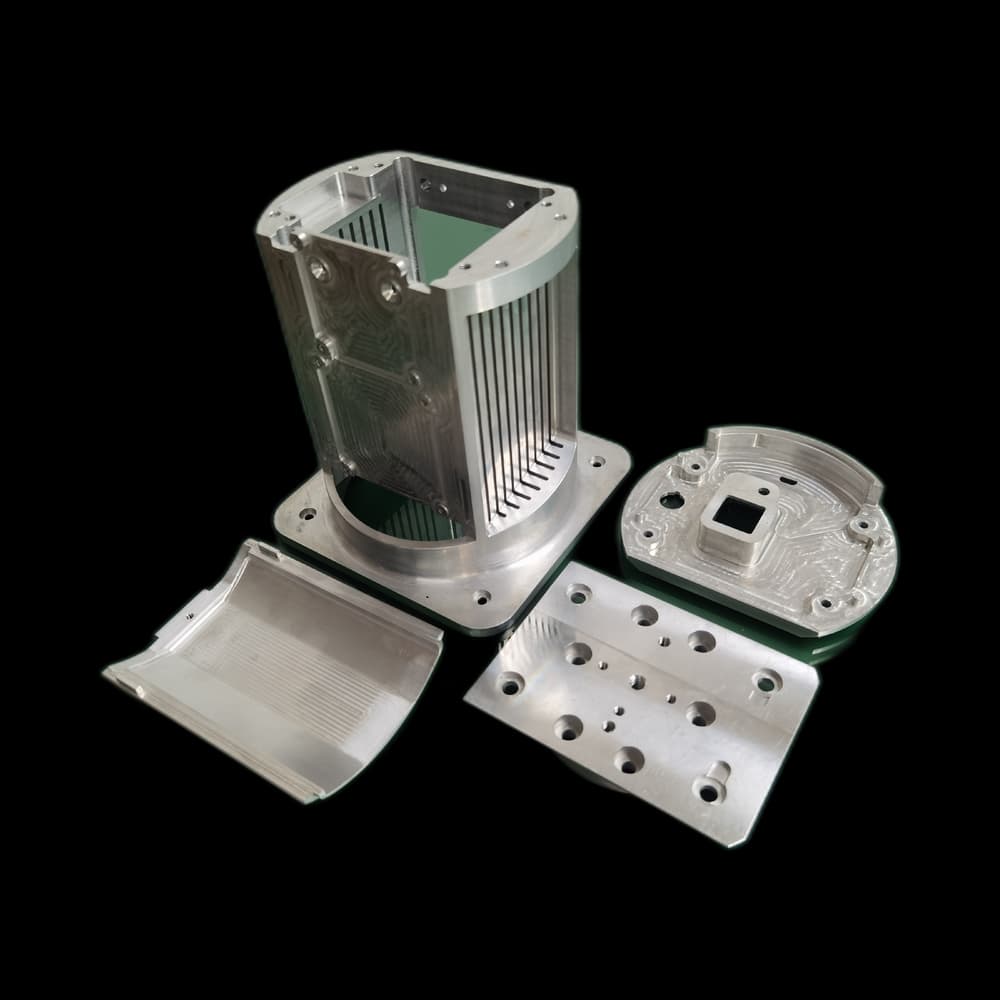
An upright finned housing sits beside separate cover plates with openings, flat faces and distributed fastening holes.
08 / APPLICATION REFERENCES
Application references connect component design with equipment context. Equipment photographs do not establish complete-system manufacture by HERUIYUN, a customer order, certification or clinical approval.
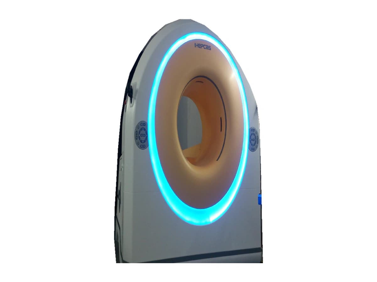
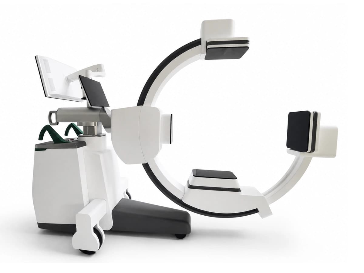
Medical equipment components are reviewed around enclosure fit, mounting structures and service access during equipment development.
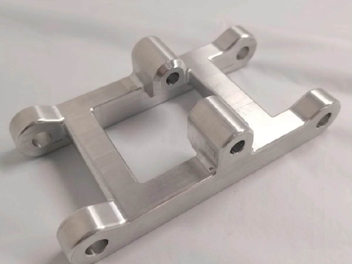
Automotive CNC components depend on defined mounting bores, structural interfaces and practical assembly access.
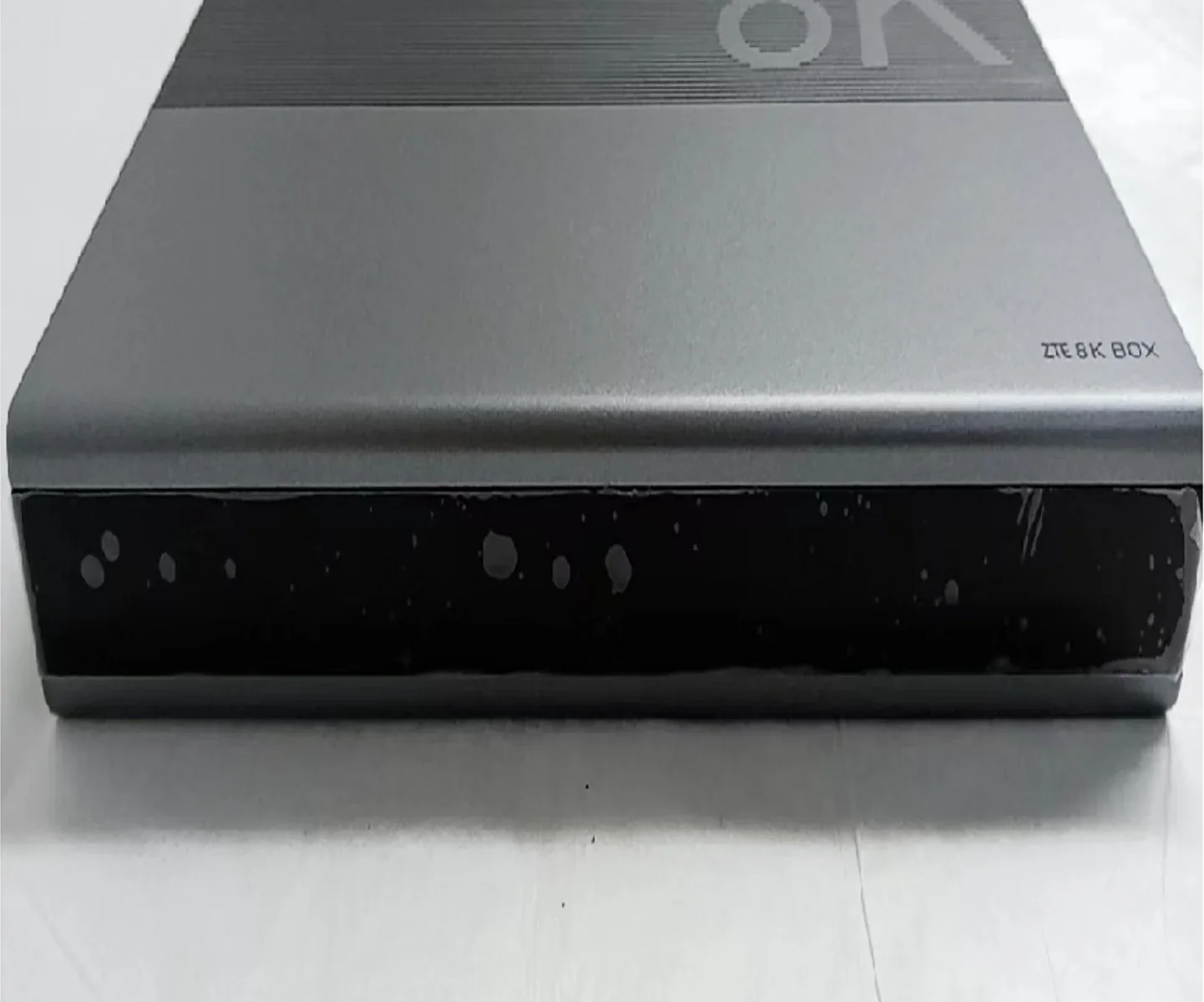
Electronics enclosures coordinate display openings, connector access, cover joints and internal packaging.

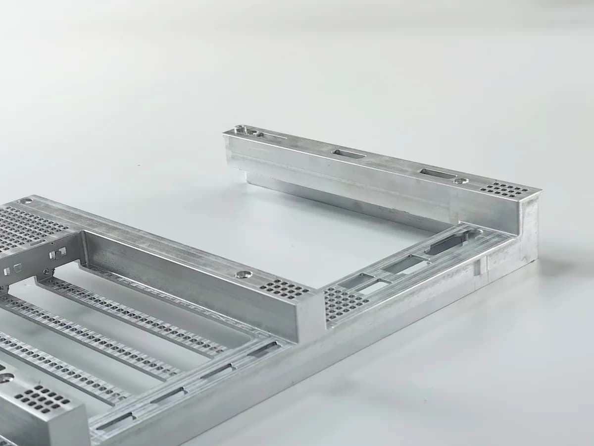
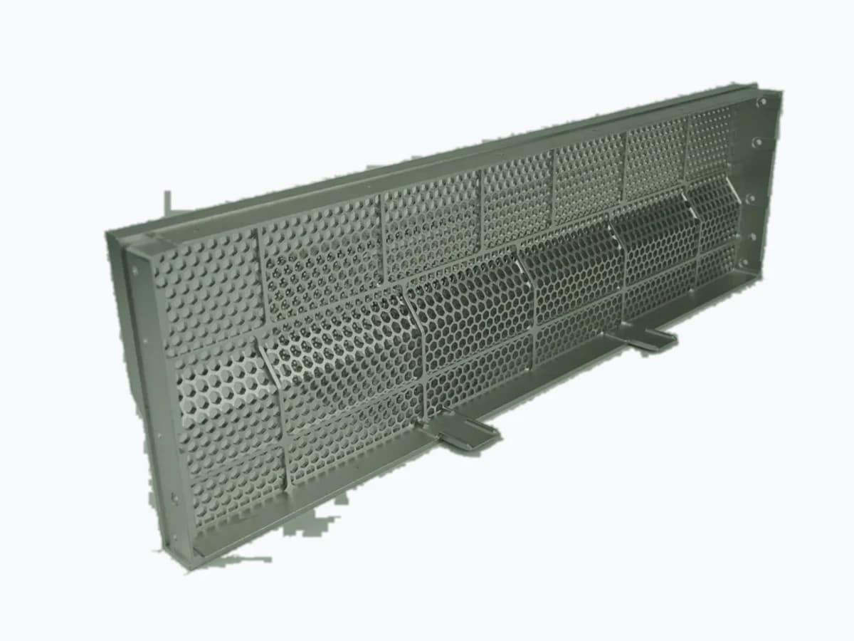
Data center hardware components include chassis structures and ventilation panels with drawing-defined mounting interfaces.
Locating plates and fixture bases illustrate industrial tooling interfaces, guide faces and mounting geometry; no inspection accuracy or certification is inferred.
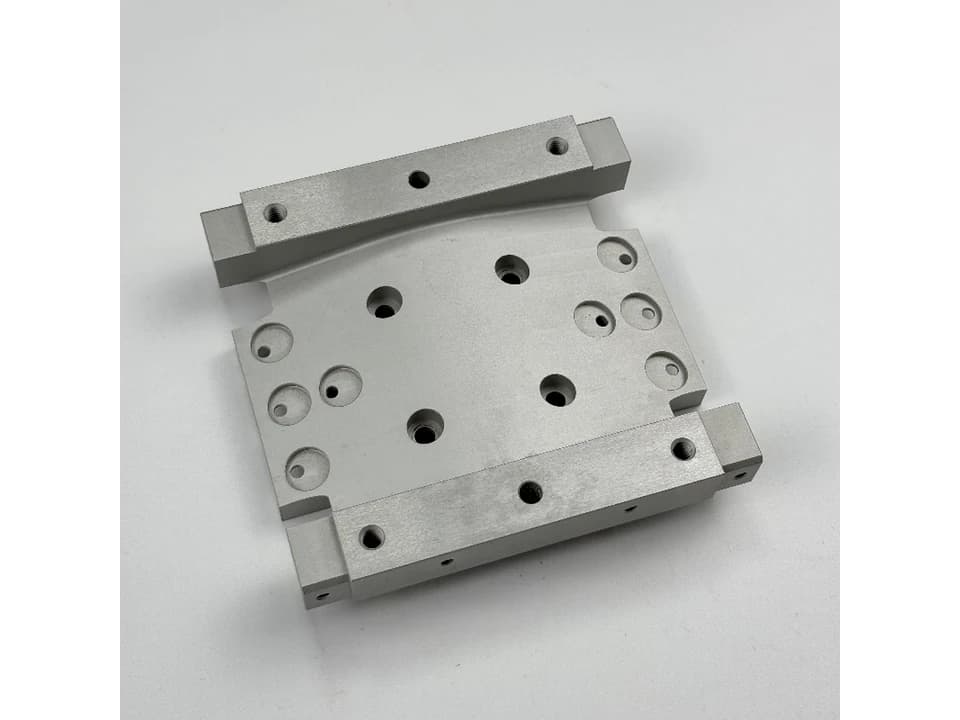
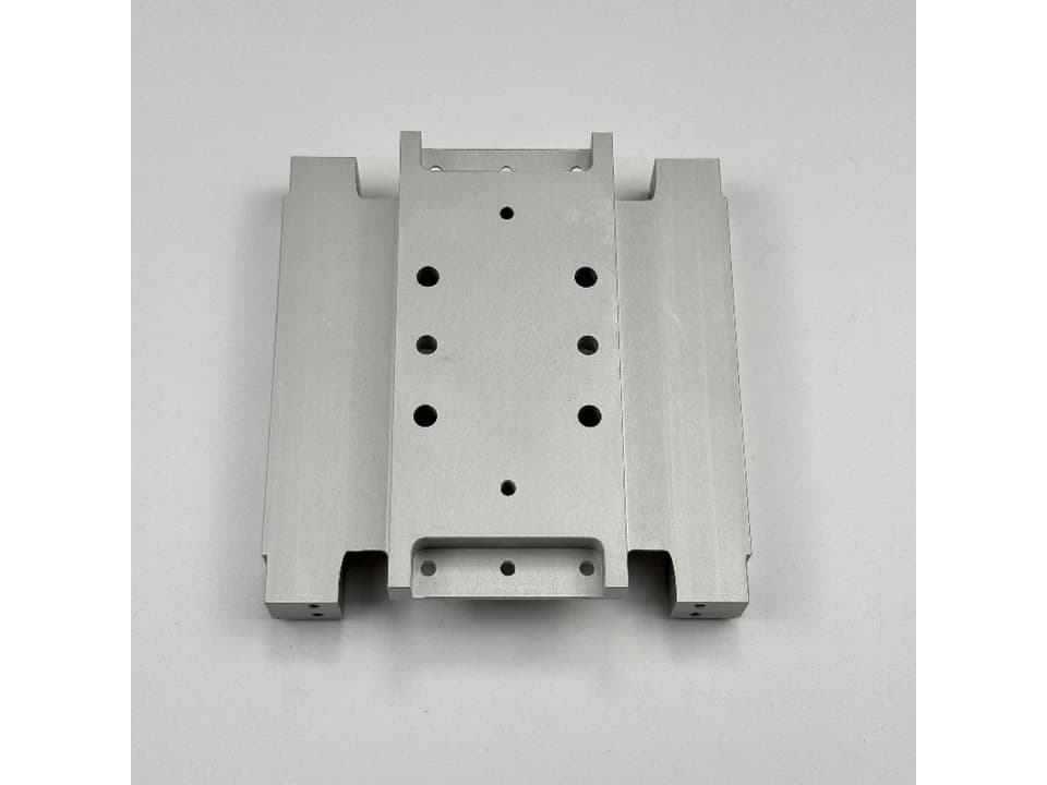
Robotic machining components and enclosure interfaces are reviewed around joint clearance, sensor access and structural assembly.


PROCESS SELECTION
Quantity alone does not determine the right process. Geometry, material, tolerances, surface requirements, design maturity and expected repeat demand should be considered together.
PROJECT CONDITION
MANUFACTURING ROUTE
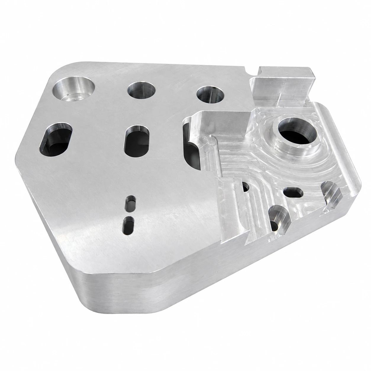
CNC MachiningSuitable where machined geometry, dimensional control and design flexibility are important.
PROJECT CONDITION
MANUFACTURING ROUTE
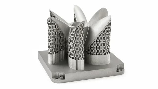
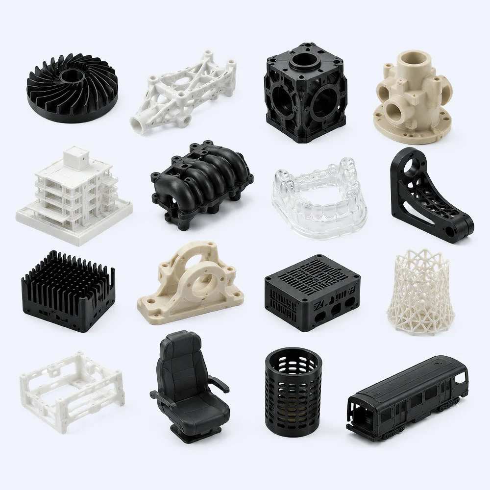
3D PrintingUseful for complex parts, low quantities and development stages where tooling is not appropriate.
PROJECT CONDITION
MANUFACTURING ROUTE
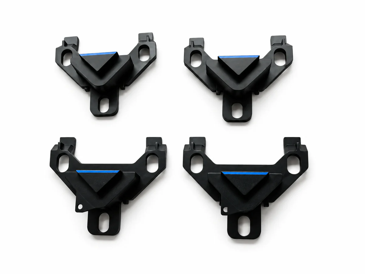
Rapid PrototypingVacuum casting or project-specific prototype molding routes may support parts that require molded appearance or behavior before dedicated production tooling.
PROJECT CONDITION
MANUFACTURING ROUTE
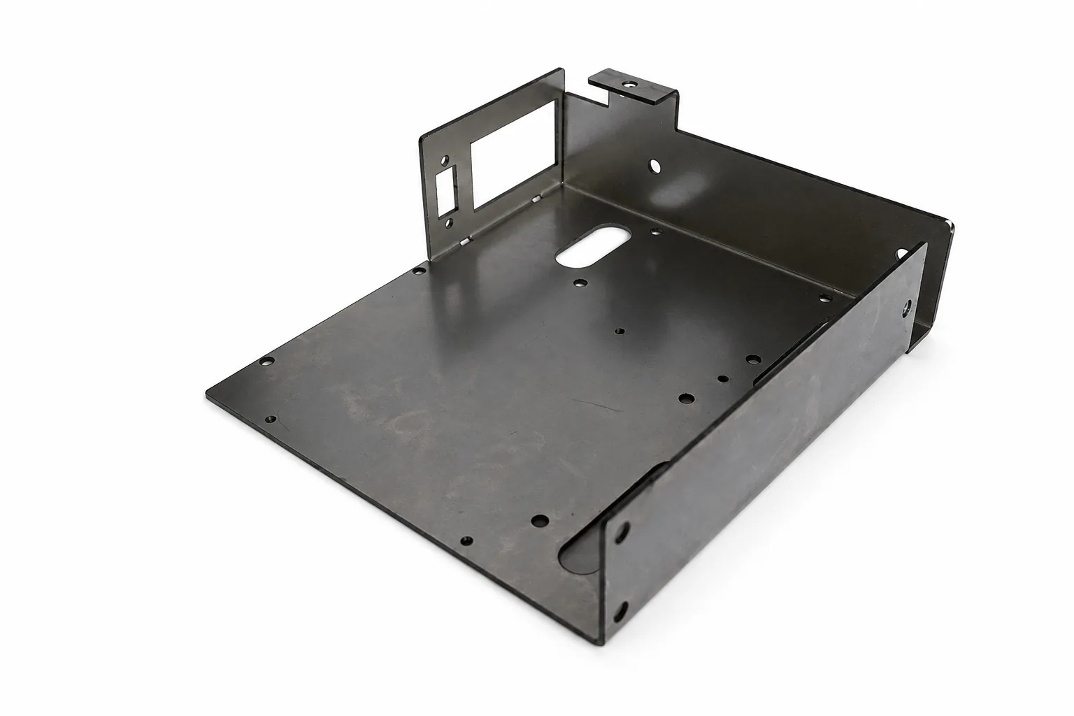
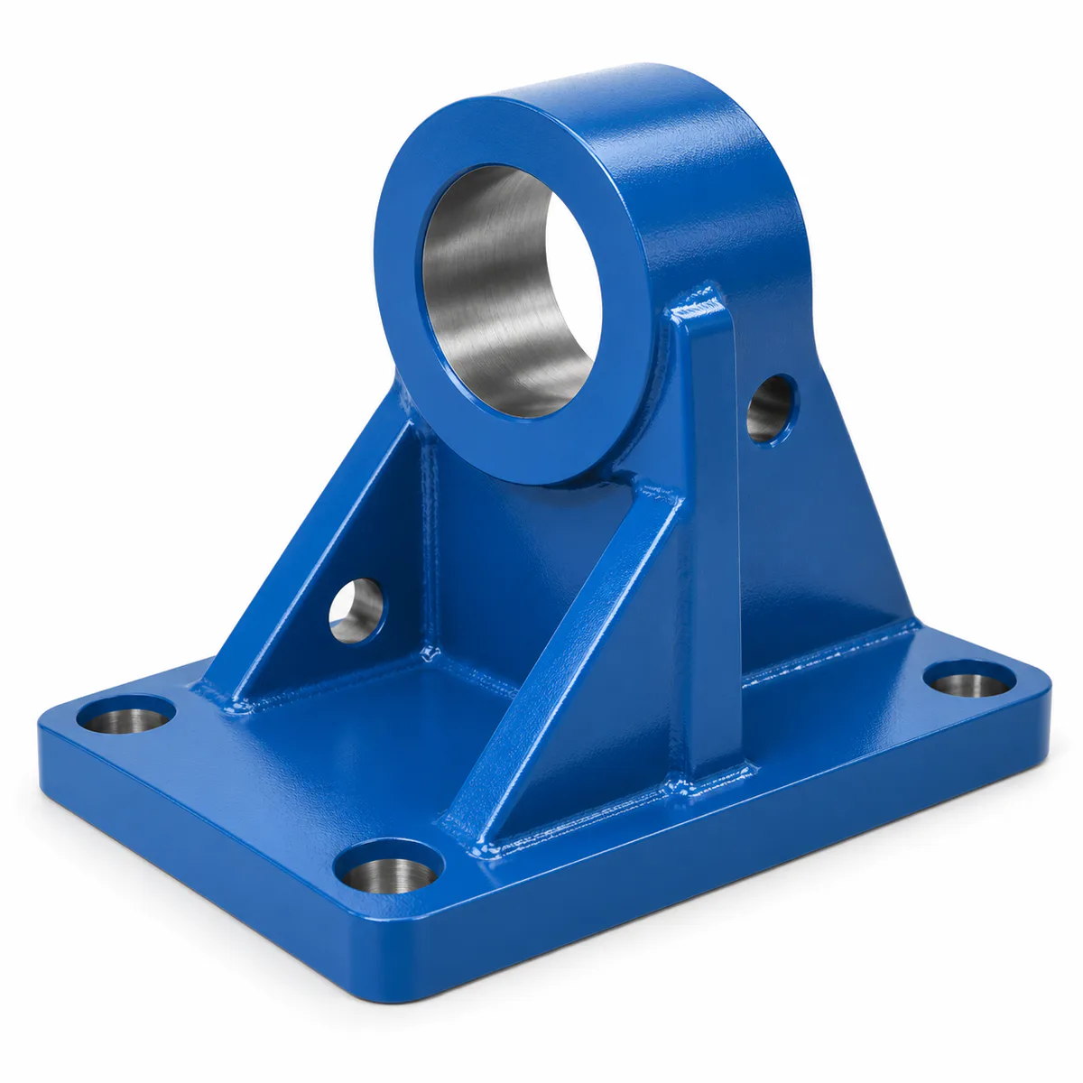
Sheet Metal FabricationSuitable for fabricated structures and enclosures where cutting, bending, joining and finishing may be combined.
PROJECT CONDITION
MANUFACTURING ROUTE
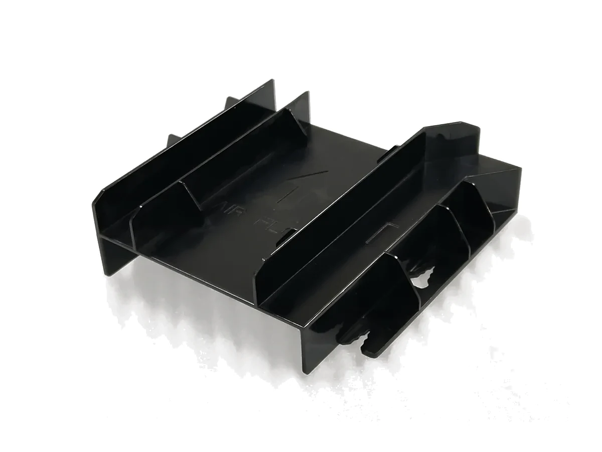
Injection MoldingConsider dedicated molding when geometry, material and expected quantity justify production tooling.
PROJECT CONDITION
MANUFACTURING ROUTE
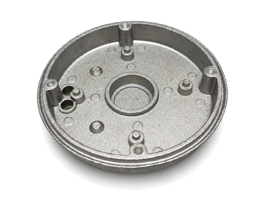
Die CastingApplicable when part design and expected volume justify a dedicated casting route.
PROJECT CONDITION
MANUFACTURING ROUTE
Surface FinishingFinishing requirements should be considered during process planning rather than treated only as a final cosmetic step.
TOOLING STRATEGY
The right tooling strategy depends on how stable the design is, how many parts are required and whether repeat demand is established.
Useful when quantities remain limited, engineering changes are still possible or dedicated tooling is not justified.
Useful when multiple molded-like parts are required but permanent production tooling is not yet the appropriate investment.
Appropriate when the design is sufficiently stable and expected repeat demand supports dedicated tooling.
PRODUCTION CONSISTENCY & REVISION CONTROL
Low-volume production is not always one part repeated many times. Industrial projects may require multiple components, variants, revisions and repeat orders in relatively small quantities.
Different components can follow different manufacturing routes within the same project.
Revisions can be reviewed against the current manufacturing route before the next batch begins.
Later batches can be reviewed against approved drawings, materials, finishes and current project requirements.
REPEAT PRODUCTION
Repeat low-volume production depends on maintaining clear project requirements between batches while still allowing controlled engineering revisions.
Confirm current revisions and critical dimensions before production.
Maintain the agreed manufacturing and finishing route where appropriate for the current revision.
Define dimensional and visual verification based on drawing and project requirements.
Confirm revisions, materials, finishes and quantities before the next production batch begins.
FAQ & PROJECT REVIEW
LOW-VOLUME FAQ
There is no universal quantity range for every project. The appropriate manufacturing route depends on part geometry, material, tolerances, tooling requirements, expected quantity and repeat demand.
PILOT · BRIDGE · REPEAT PRODUCTION