
Rigid Polyurethane
Reviewed for housings and covers that need stable molded geometry, defined interfaces and a rigid structural response.
- Housing shells
- Covers
- Mounting geometry
Produce large, complex polyurethane housings and structural components through a low-pressure reactive molding route designed for development and low-volume manufacturing.
HERUIYUN reviews part size, wall geometry, polyurethane behavior, tooling strategy, inserts, surface requirements and critical interfaces before confirming the RIM route.
Get a RIM Quote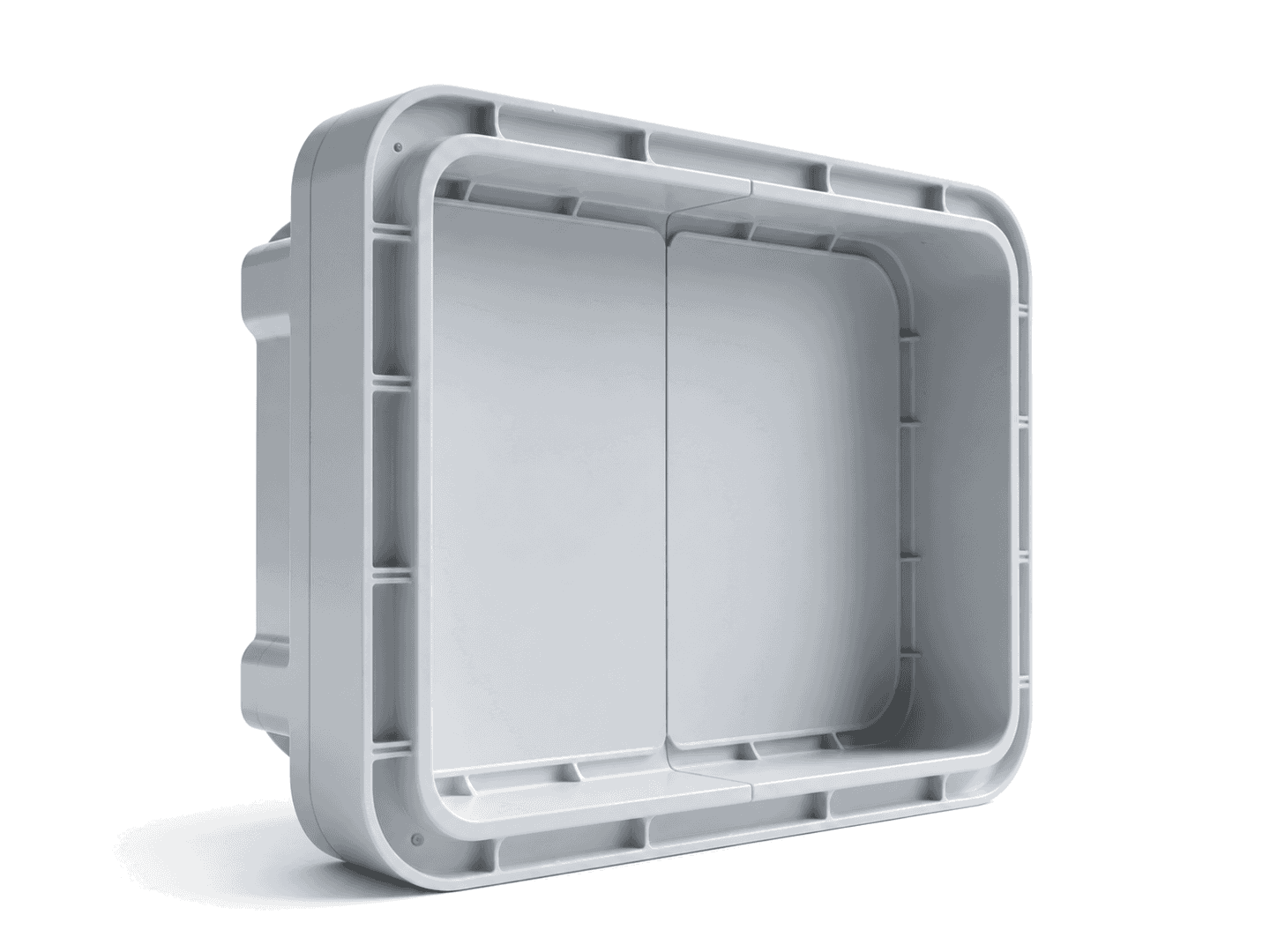
Reaction Injection Molding becomes useful when the development part is a large housing, structural shell or integrated polyurethane component that needs more design freedom than a conventional small molded part and a more production-oriented route than repeated prototype casting.
Create large enclosures, equipment covers and molded shells where a single integrated part can replace multiple fabricated components.
Review substantial sections and controlled wall transitions around stiffness, material flow, cure behavior and critical interfaces.
Combine visible surfaces, ribs, bosses, openings and mounting geometry into a more integrated molded architecture.
Use a dedicated low-pressure polyurethane route when development has moved beyond repeated prototype casting but conventional high-pressure tooling is not yet the right commitment.
RIM capability is confirmed after reviewing part size, geometry, polyurethane behavior, tooling, flow, venting, finish and critical interfaces.
Final capability is project-specific and confirmed during engineering review. No universal part size, wall thickness, tolerance, shrinkage or production quantity applies to every RIM project.
RIM forms the part through a controlled chemical reaction rather than by forcing molten thermoplastic into a conventional high-pressure mold.
Meter the liquid reactive components according to the selected polyurethane system and project requirements.
Combine the reactive components immediately before molding so the material system is prepared for controlled filling and cure.
Introduce the low-viscosity mixture into the project-specific mold through the planned gate and flow path.
Allow the material to react and cure inside the tool while wall distribution, temperature and geometry influence final behavior.
Remove the cured part, complete approved trimming or finishing and inspect drawing-defined surfaces and interfaces.
Polyurethane system selection follows the required structural response, flexibility, surface, color, cure behavior and downstream finishing—not an unsupported equivalence to a named production thermoplastic.
Reviewed for housings and covers that need stable molded geometry, defined interfaces and a rigid structural response.
Reviewed when section design, stiffness and substantial molded geometry are central to the part architecture.
Reviewed where controlled flexibility or impact-related behavior is part of the functional requirement.
Selected around the required structural, surface, color, cure and downstream finishing objectives rather than by a generic material-equivalence claim.
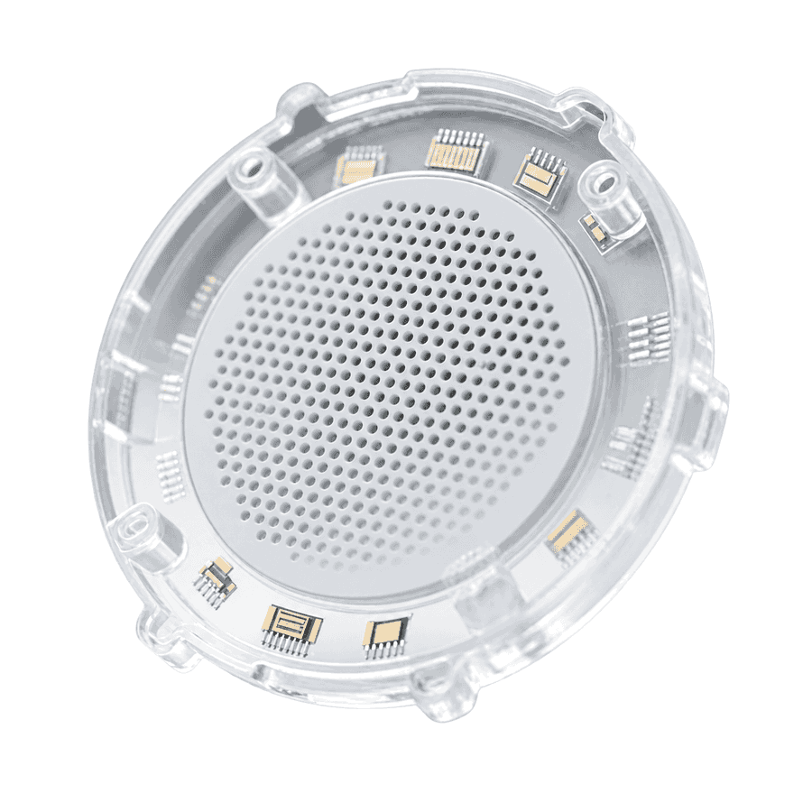
Clear / visual-transmission review
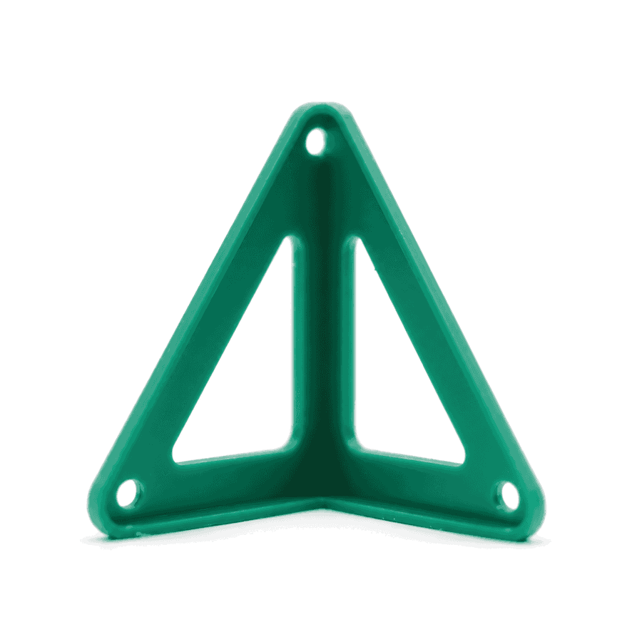
Pigmented rigid polyurethane review
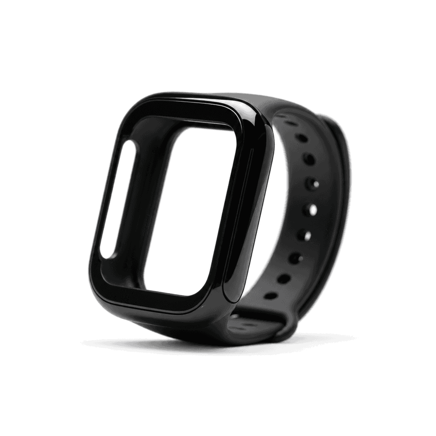
Flexible polyurethane behavior review
These images are material and finish references, not verified RIM production cases. Material availability and final behavior are confirmed per project.
RIM is most compelling when the product is a large molded structure with integrated cosmetic surfaces, ribs, bosses or mounting features—not when the job is simply to duplicate a small plastic prototype.
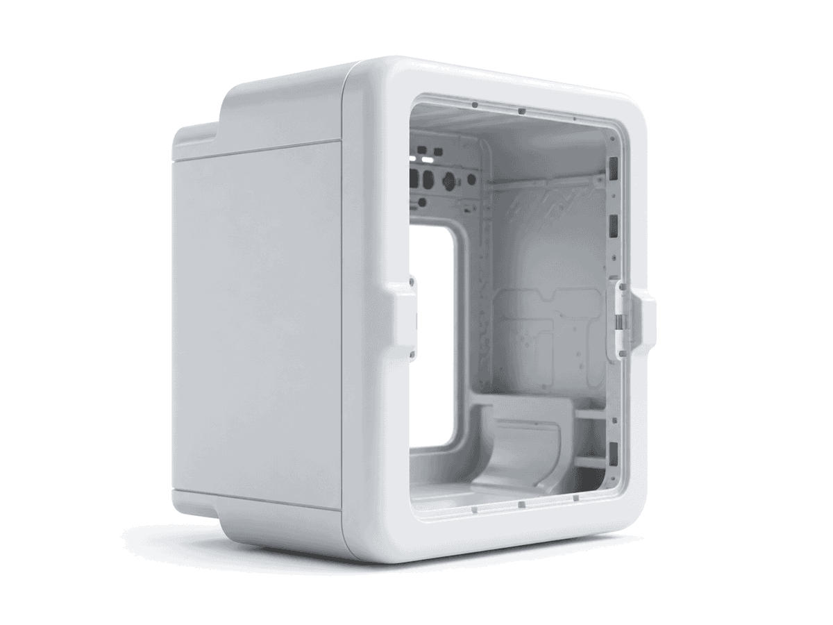
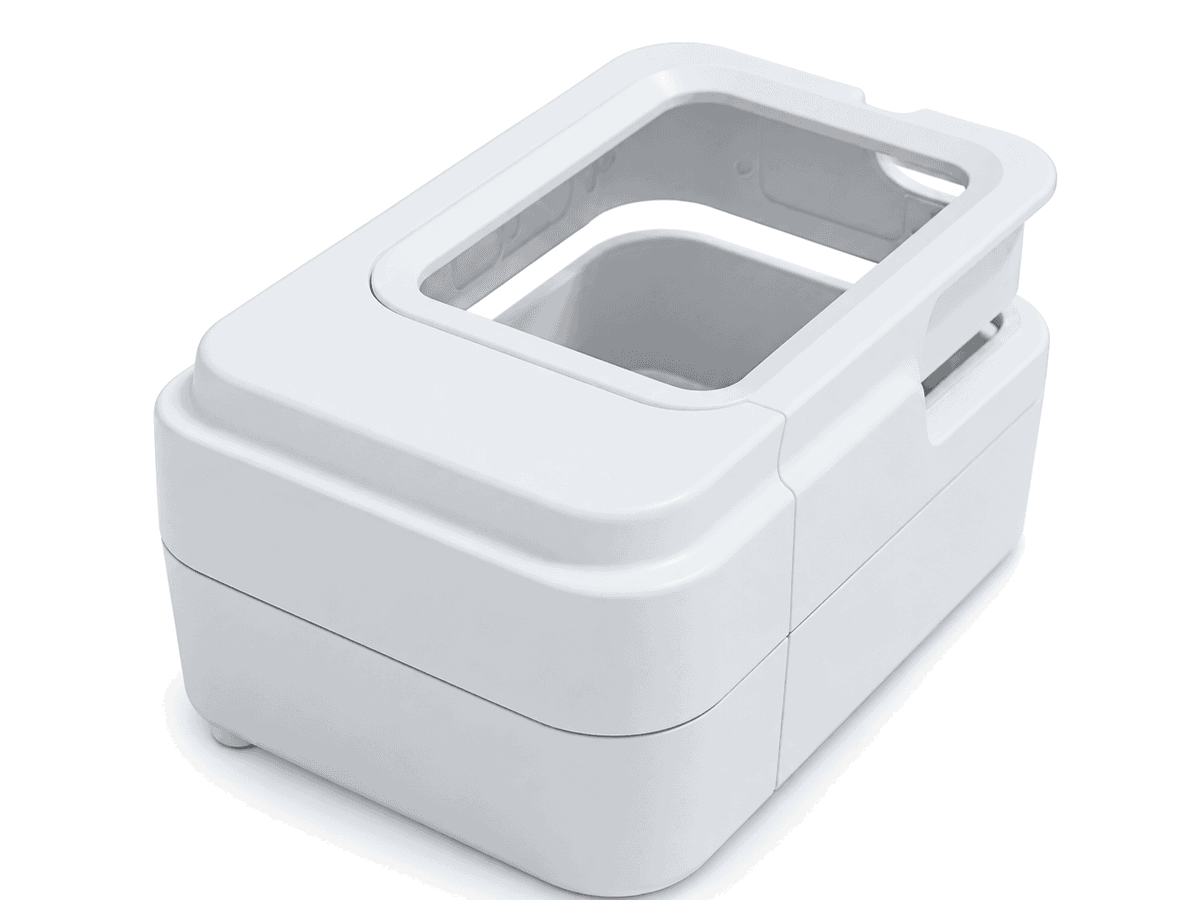
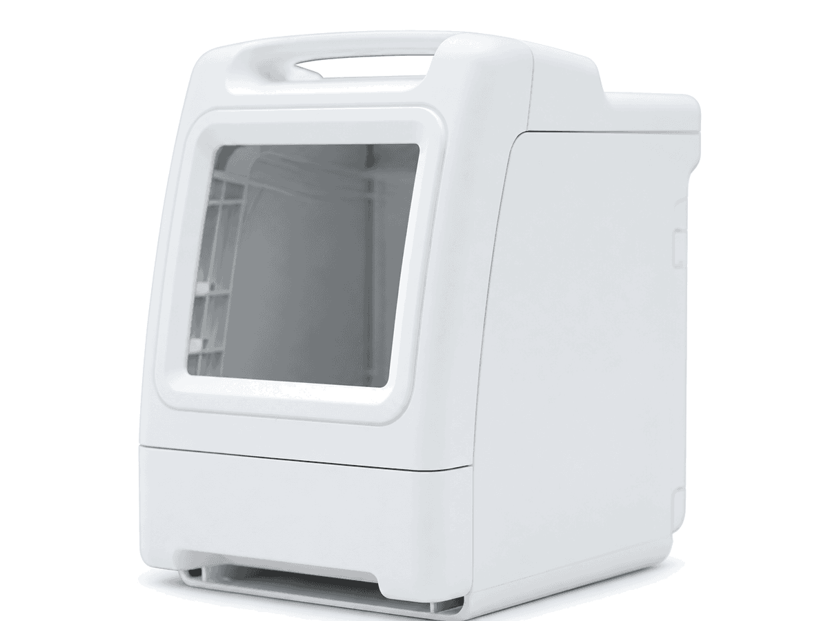
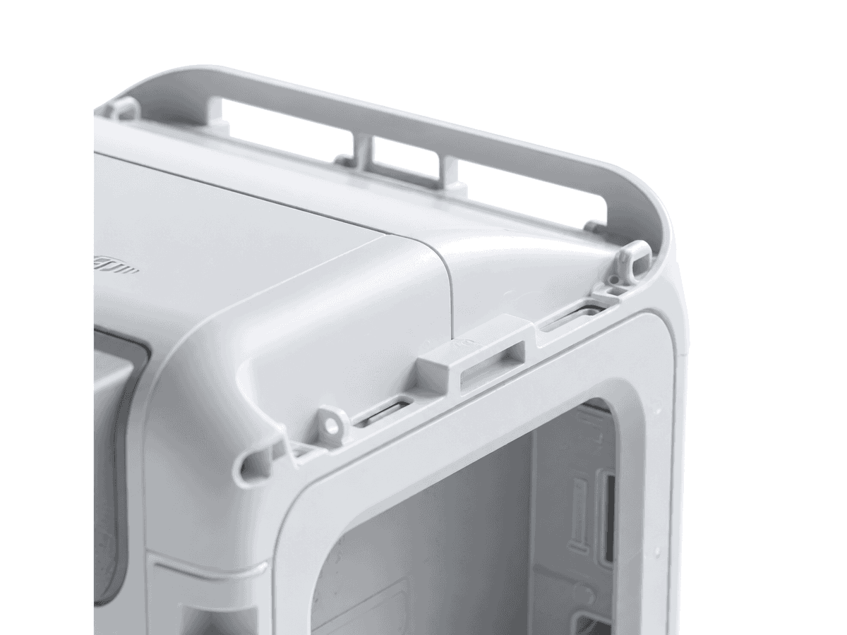
Treat the housing as an integrated structure. Wall distribution, reinforcement, interfaces and part consolidation must support the same material-flow and tooling strategy.
Use wall transitions deliberately because local thickness influences flow, cure, shrinkage, stiffness and dimensional behavior.
Place ribs around the intended load path and molding strategy, with attention to local mass, intersections and visible-surface effects.
Review boss geometry, local support and interface location together with inserts, tool access and assembly loads.
Combine compatible housing, bracket and interface functions when one integrated molded structure improves the product architecture.
Hardware integration can reduce secondary brackets and assembly steps, but only when insert compatibility, tool access, load direction and inspection requirements are understood before tooling.
Insert type, location, retention requirement and load direction must be defined before the tool and molding sequence are confirmed.
Project-specific plates may be reviewed where their material, position, load path and encapsulation strategy are compatible with the selected system.
Components placed in the mold require clear compatibility, protection, access and inspection requirements.
Hardware may be more reliable when installed after molding if encapsulation complicates tooling, inspection or future service.
Use the molding review to reduce unnecessary secondary brackets while keeping serviceable and critical interfaces explicit.
Integrated hardware is reviewed per project. It is not assumed that every insert or component should be encapsulated during molding.
Avoid treating one wall value as universal; use transitions that support the selected material, flow path and structural objective.
Balance stiffness and mounting needs against local mass, flow interruption and visible-surface risk.
Use deliberate internal and external transitions to support flow, release and structural continuity.
Review core strategy, local flow, edge condition and any downstream machining required for critical openings.
Define tool opening, release direction and any side-action or secondary strategy before finalizing undercut geometry.
Identify the hardware, tolerance, load direction and functional datum rather than leaving interface intent implicit in the CAD model.
A large molded structure succeeds only when the tool, gate, flow path and vents are reviewed as one system around the approved geometry.
Tool material and construction are selected around part size, surface, quantity, cure behavior and dimensional priorities.
Gate position should support the intended fill path while keeping local witness or cleanup away from sensitive areas where practical.
Large structures need a planned material path around wall transitions, ribs, bosses, inserts and remote features.
Vents are planned at likely air-trap and end-of-fill locations to support complete filling of the approved geometry.
Mating surfaces, mounting points, openings and dimensional datums should guide tooling and downstream inspection priorities.
Surface strategy begins with the tool and material system, then extends into any project-specific painting, coating, marking or final assembly route.
Surface outcome depends on the polyurethane system, tool surface, flow, cure and the location of gates, vents and parting features.
Project-specific texture can be reviewed when the tool construction, geometry and cosmetic zone support the intended result.
Secondary paint or coating is confirmed around material compatibility, preparation, geometry and the required visual outcome.
Marking, hardware installation and assembly operations are reviewed as downstream requirements rather than assumed process defaults.
Dimensional capability emerges from the interaction of part size, polyurethane system, wall distribution, tool construction, cure behavior and feature location.
Larger dimensions can accumulate more absolute variation and require clearly defined critical interfaces.
Reactive polyurethane systems differ in cure behavior and dimensional response.
Heavy sections and major transitions can influence local cure, shrinkage and deformation.
Tool material, support, temperature and repeatability contribute to the molded outcome.
Cure and shrinkage must be evaluated for the selected material, geometry and process rather than assigned one universal value.
Datums, mounting points and assembly interfaces should be identified on the drawing and prioritized during review.
Critical dimensions, datums and assembly interfaces must be identified on the drawing. Final tolerance and shrinkage strategy are confirmed after engineering review.
Choose the route around part format, material intent, tooling commitment and the current development stage—not a fixed quantity threshold.
| Attribute | Vacuum Casting | RIM | Injection Molding |
|---|---|---|---|
| Material Route | Cast polyurethane from a silicone mold | Reactive polyurethane system | Production thermoplastic |
| Tooling | Master pattern + silicone soft tooling | Project-specific low-pressure mold | Conventional high-pressure production tooling |
| Typical Part Format | Repeated prototype parts | Large integrated housings and structures | Production molded components |
| Geometry Focus | Replication and cosmetic validation | Variable walls, ribs, bosses and consolidation | Thermoplastic production design |
| Development Stage | Prototype / small-batch validation | Development / low-volume bridge | Pilot / production |
| Tooling Commitment | Limited-life soft tooling | Dedicated project tooling | Higher production-tooling commitment |
| Best Reason to Choose | Repeat approved prototype geometry | Create a substantial integrated molded structure | Support long-term thermoplastic production |
Align inspection and project inputs with the interfaces, surfaces and structural behavior that matter for the development objective.
Review drawing-defined overall geometry and dimensional priorities according to the agreed inspection plan.
Verify critical datums, holes, openings and mating surfaces that control installation and function.
Review insert location, orientation and retention requirements where hardware is integrated.
Review the large molded form for project-defined shape and distortion concerns.
Evaluate agreed visible surfaces, texture, paint or coating requirements without assuming one universal cosmetic standard.
Confirm the interfaces needed for the housing to assemble with mating parts or hardware.
Provide the latest complete part geometry, including structural features, openings and intended interfaces.
Identify critical dimensions, datums, tolerances, cosmetic zones and inspection requirements.
State the expected quantity and whether the project is engineering validation, pilot or bridge manufacturing.
Define required rigid, structural, elastomeric or other project-specific polyurethane behavior.
Define as-molded, textured, painted, coated or other cosmetic expectations.
Provide exact insert / hardware requirements, load direction and interface location where relevant.
Use the engineering review to align the polyurethane system, large-part geometry, inserts, tool strategy and critical interfaces.
Reaction Injection Molding is a low-pressure molding process in which liquid reactive components are metered, mixed and introduced into a mold, where they react and cure into a polyurethane part. It is commonly considered for larger housings and integrated molded structures where part size and structural geometry are important.
RIM uses low-viscosity reactive material systems that cure in the mold, while conventional injection molding typically injects molten thermoplastic at much higher pressure. The different process physics lead to different material choices, tooling strategies, part-size economics and design priorities.
Vacuum Casting is useful when the main goal is repeated prototype replication from a master pattern. RIM becomes more relevant when the product is a larger structural housing or integrated polyurethane component that needs a dedicated low-pressure mold and a more production-oriented bridge route.
Large housings and covers are an important RIM use case because the process can support project-specific tooling for substantial molded structures. Final feasibility still depends on part size, wall geometry, material behavior, tooling and critical interface requirements.
Variable wall geometry can be reviewed in RIM, but it should be designed deliberately. Major thickness transitions influence material flow, cure, shrinkage, stiffness and final dimensional behavior, so they require engineering review rather than a universal wall-thickness rule.
Project-specific inserts, mounting plates or other interfaces may be reviewed when material compatibility, tool access, load direction and final assembly requirements are defined. Some hardware may be better installed after molding rather than encapsulated in the tool.
RIM projects may be reviewed for as-molded surfaces, mold texture, project-specific paint or coating and downstream marking or assembly. Final availability depends on the polyurethane system, tool surface, geometry and cosmetic requirements.
The transition should be reviewed when production volume, material requirements, repeatability, tooling economics or long-term manufacturing strategy make a conventional thermoplastic molding route more appropriate. The decision is project-specific rather than based on one fixed quantity threshold.
Upload your CAD and drawing for review of part size, polyurethane behavior, wall geometry, tooling strategy, inserts, surface requirements and critical interfaces.