Shaft Interfaces
Define both shaft diameters, engagement lengths and fixing details. Do not assume the two bores or their assembly requirements are identical.
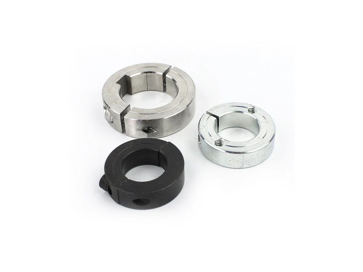
Slotted metal coupling components with shaft bores and fixing interfaces. Define the coupling architecture, mating shafts and operating requirements for engineering review.
Upload CAD Drawings for a Quote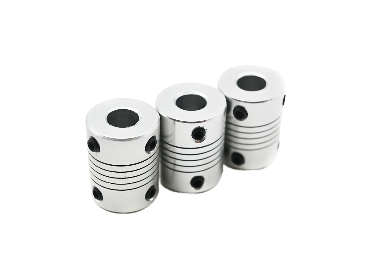
Define both shaft diameters, engagement lengths and fixing details. Do not assume the two bores or their assembly requirements are identical.
Slots and the remaining sections form part of the coupling design. Specify their width, termination and edge condition without inferring flexibility from appearance alone.
Locate clamping or set-screw holes relative to the shaft bores. Include assembly access and hardware requirements in the drawing.
State speed, load direction and expected movement for design review. These are inputs for assessment, not performance guarantees from machining a similar shape.
Review bore machining, slot access and fastening features as a connected sequence. Thin remaining sections and interrupted surfaces require drawing-specific fixturing, deburring and inspection planning.
Review corrosion exposure, slot-edge condition and the proposed material state. Coupling behaviour must be assessed for the completed design.
Specify material condition and finishing requirements at bores and fasteners. Strength and fatigue requirements need separate design verification.
Consider rotating mass, stiffness and clamping features. Review any anodizing allowance at the shaft interfaces and slot edges.
Treat brass as a drawing-dependent candidate for applicable coupling subcomponents. Do not assume it is suitable for every slotted flexible design.
These grades are engineering selection candidates, not a statement of stock availability or verified capability for every material condition. Material, heat treatment and inspection requirements are subject to factory confirmation against the drawing.
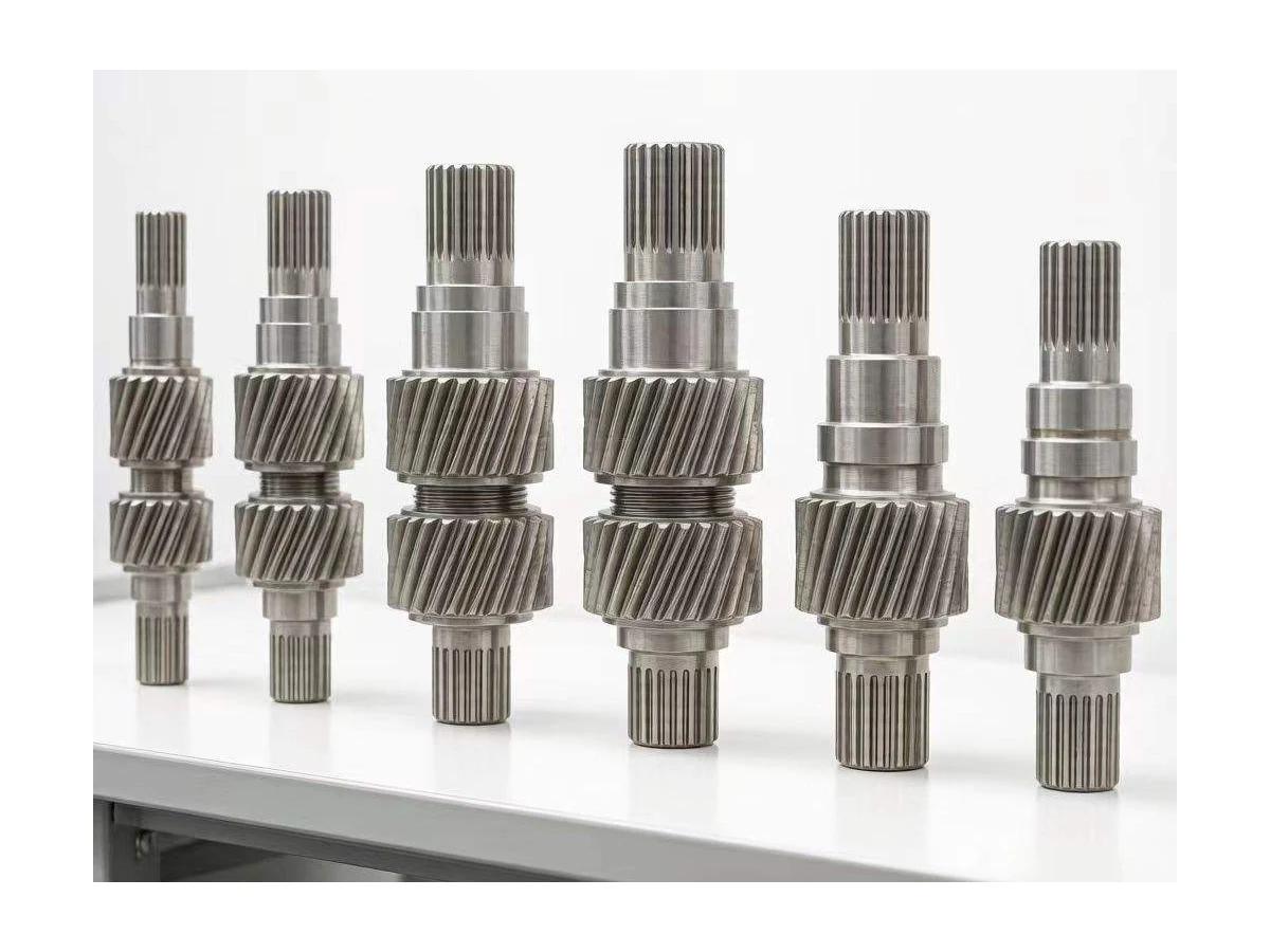
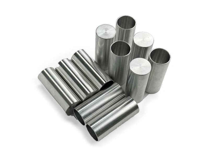
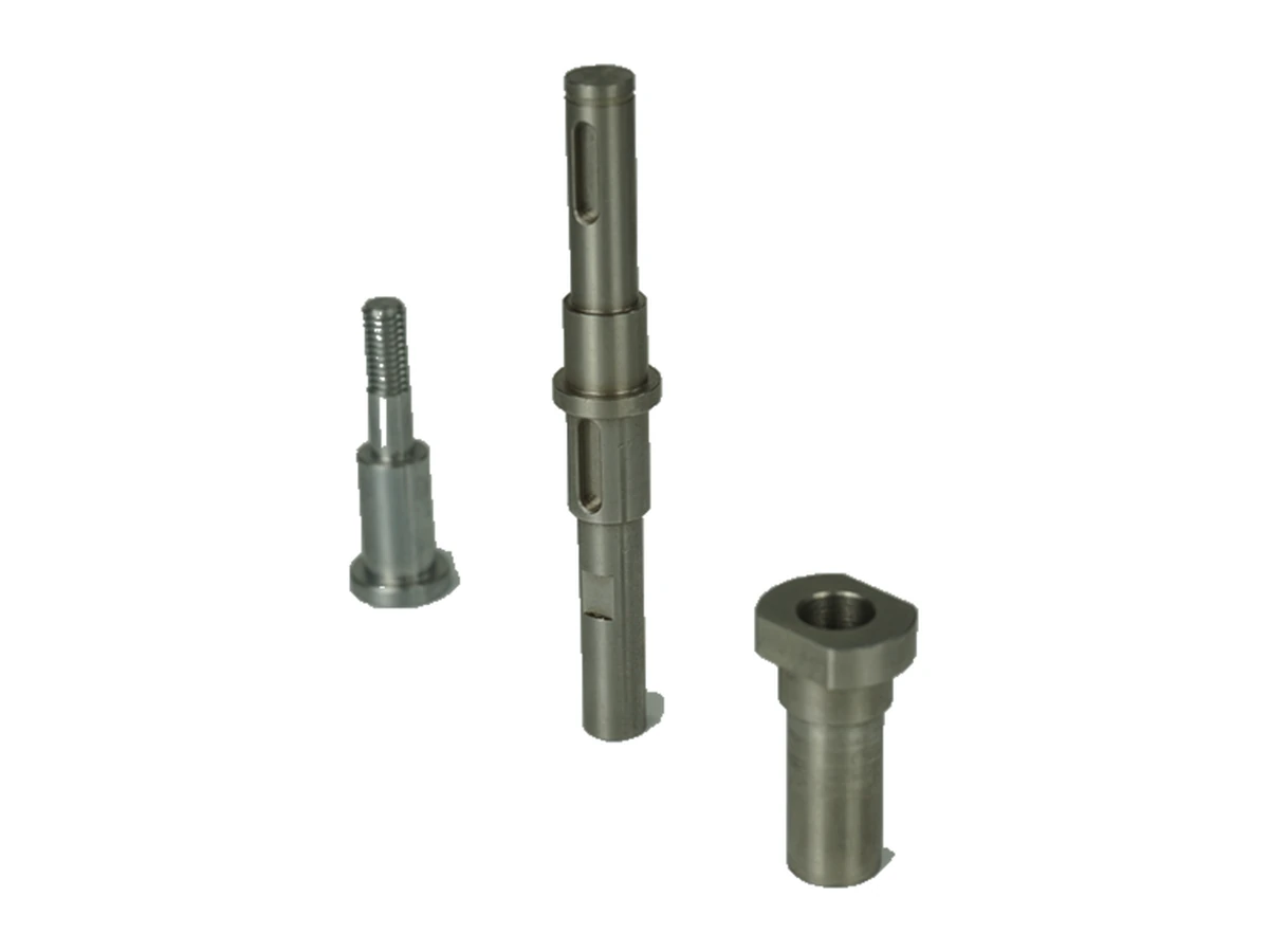
Explore CNC Metals & MaterialsUse the dimensioned drawing to define these requirements. Photographs illustrate visible geometry; they do not establish a standard size, material grade or performance rating.
Couplings connect rotating shafts within a drive. Shaft fit, retention and the selected coupling design must be reviewed alongside alignment and operating duty.
Positioning equipment may use compact coupling components near bearings and drive units. Buyers should define installation clearances and the required motion response without assuming zero backlash.
Prototype couplings may explore bore or mounting variations. Structural and operating validation remain separate from checking that the machined geometry matches the drawing.
Review how slots affect support during machining and inspection. Avoid specifying inaccessible sharp internal corners.
Choose accessible datums and agree the finished bore checks. Fastener installation may change an assembled bore condition.
Identify slot intersections and screw breakouts that need controlled edge treatment. Do not rely on a general finish note for critical interfaces.
Confirm the intended operating envelope and validation responsibility. No torque, fatigue, balance or misalignment rating is inferred from the photograph.
Send the CAD model and project requirements for manufacturing review.
Upload CAD Drawings for a Quote