Paired Diameters
The bore and outside diameter form separate mating interfaces. Identify their required relationship and final condition on the drawing.
Drawing-defined cylindrical bushings and sleeves with controlled inner and outer interfaces. Review wall thickness, seating faces, fits and material condition for the actual assembly.
Upload CAD Drawings for a Quote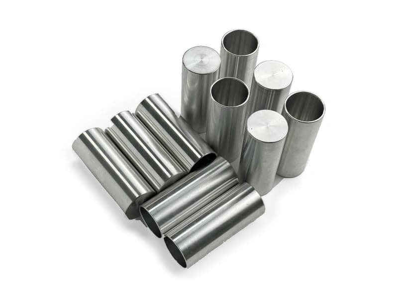
The bore and outside diameter form separate mating interfaces. Identify their required relationship and final condition on the drawing.
Define wall thickness, length and any shoulders or flanges. Slender or thin-wall geometry needs a suitable support and measurement plan.
Show end-face requirements, lead-ins and edge breaks. These features affect assembly without replacing the specified fit.
Relate the bore, outside diameter and working faces to the intended function. Specify which features guide, locate or space the mating components.
Review turning and bore finishing around the wall thickness and material condition. Clamping, tool access and inspection need to preserve the relationship between the inner and outer surfaces without assuming an unspecified fit class.
Consider corrosion exposure and the condition of both mating surfaces. Specify finish and material state for the actual assembly.
Review wear and treatment requirements together. Identify dimensions that require acceptance in the final material condition.
Review machinability and contact conditions with the mating component. Material selection alone does not establish bearing or lubrication performance.
Review temperature, loading and dimensional behaviour. Define the fit at the service and inspection conditions relevant to the design.
These grades are engineering selection candidates, not a statement of stock availability or verified capability for every material condition. Material, heat treatment and inspection requirements are subject to factory confirmation against the drawing.
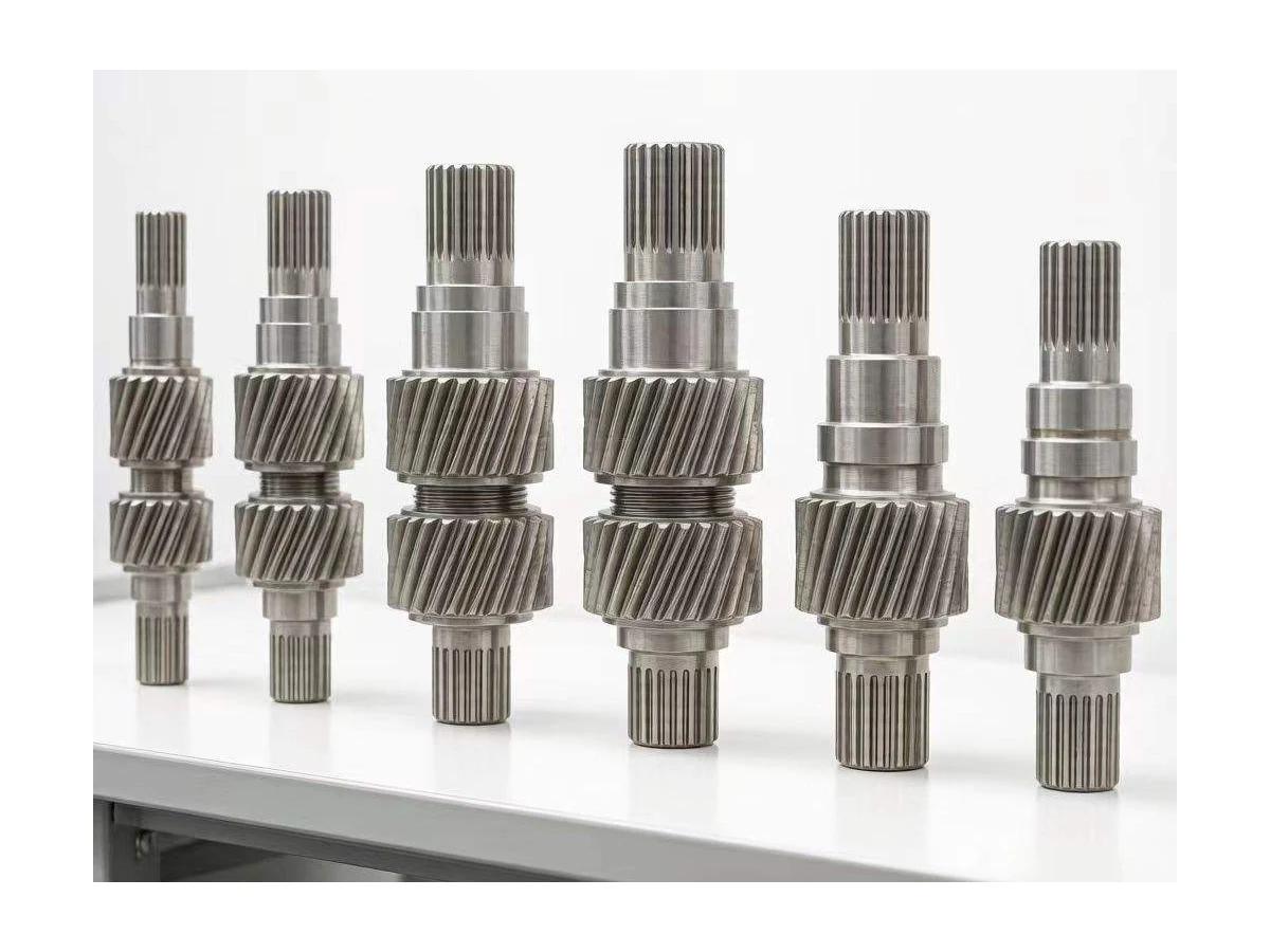
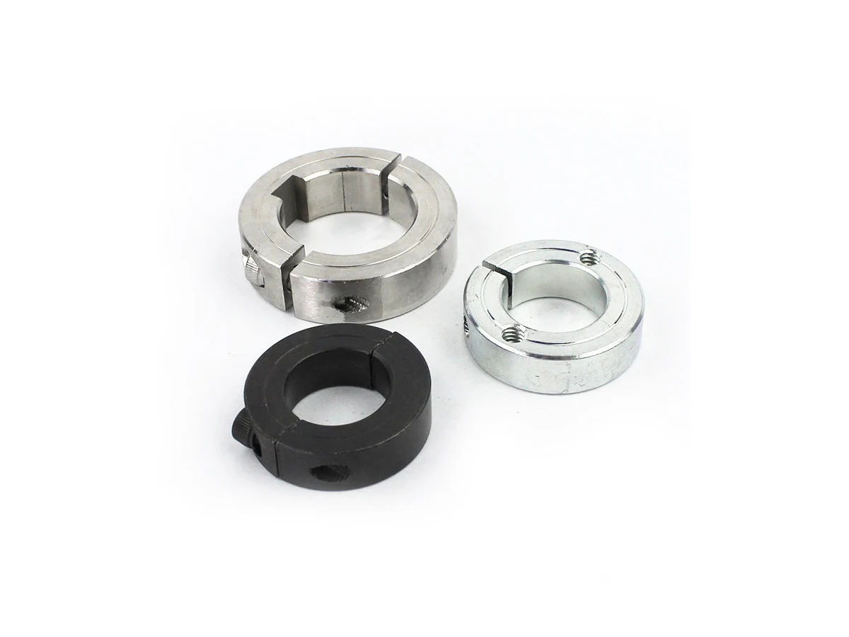
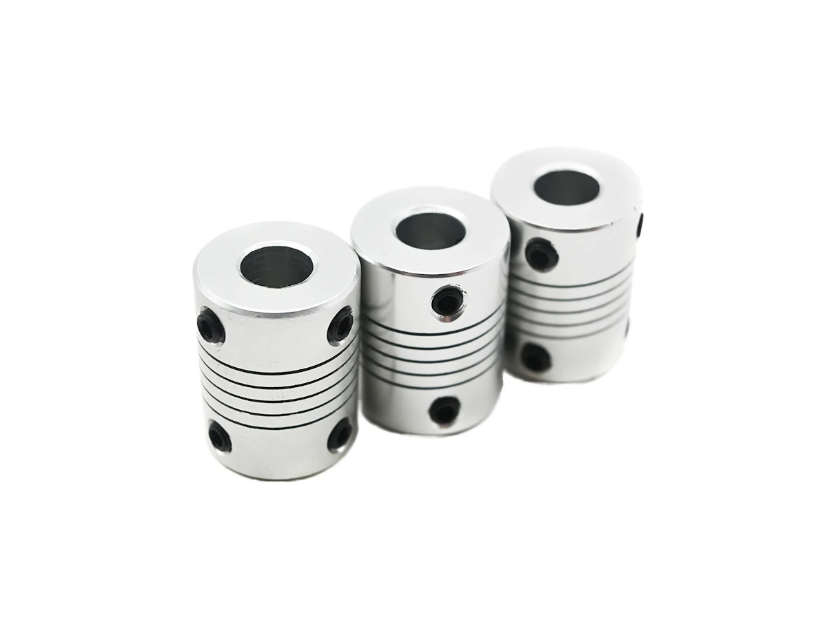
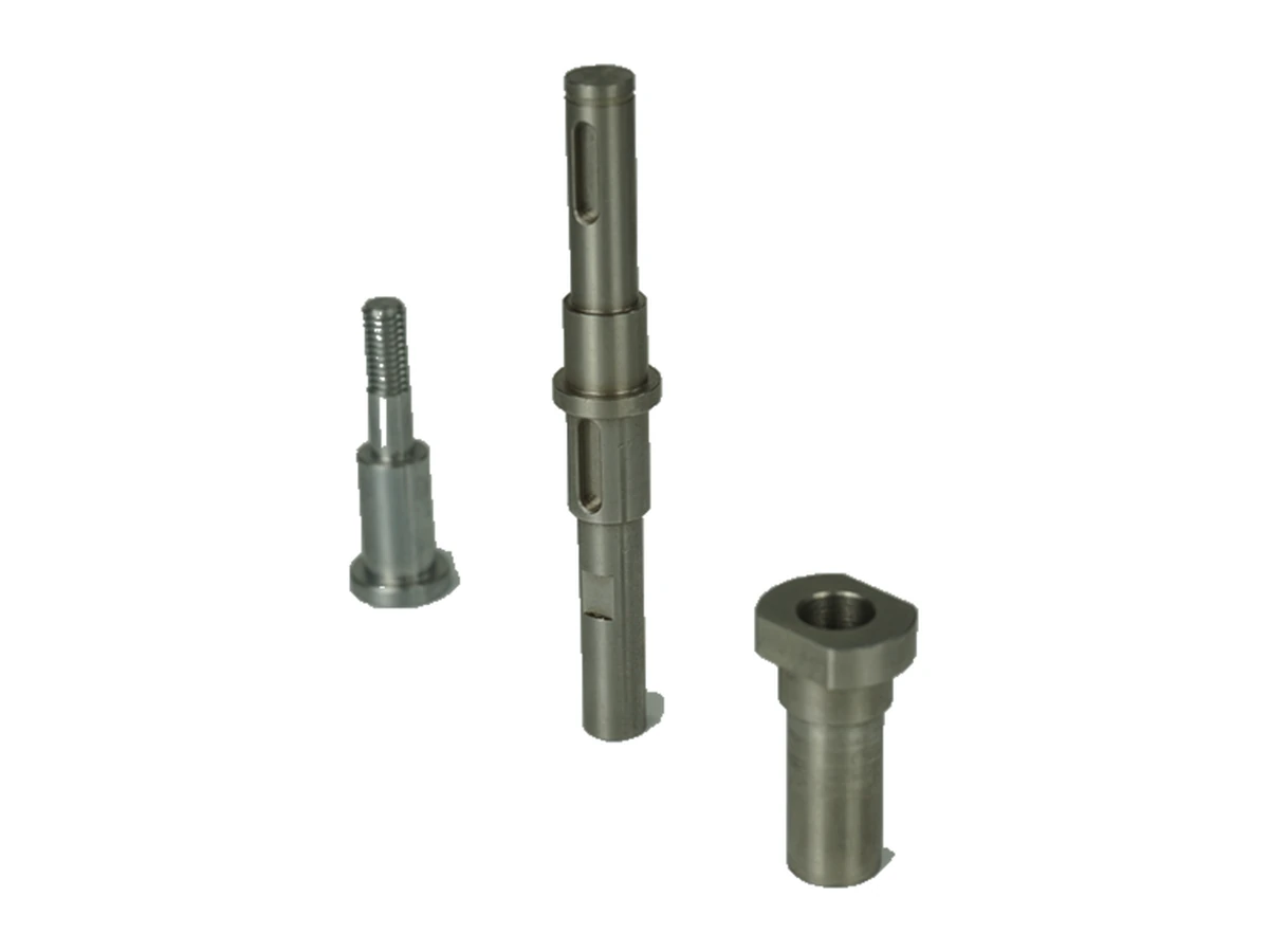
Explore CNC Metals & MaterialsUse the dimensioned drawing to define these requirements. Photographs illustrate visible geometry; they do not establish a standard size, material grade or performance rating.
A bushing can guide a mating pin or shaft within an assembly. Define contact length, fit and operating conditions rather than assuming all sleeves are bearing components.
Sleeves may set spacing or locate parts around a fastener or shaft. End-face relationships and assembly stack dimensions should be clear to the supplier.
Some assemblies use a replaceable sleeve at a wear-sensitive interface. Review the housing fit, removal method and service material pairing before finalizing the part drawing.
Review wall thickness, clamping and measurement together. Avoid a drawing that leaves the inspection condition ambiguous.
Define full-depth bore requirements and internal reliefs. Tool access and depth may influence the proposed finishing route.
State the required condition after coating or treatment. Identify surfaces that must remain controlled during finishing.
Agree the dimensional checks and any requested assembly trials. No universal precision level is claimed for every bushing.
Send the CAD model and project requirements for manufacturing review.
Upload CAD Drawings for a Quote