Spline Profile
Specify the tooth form, tooth count and governing drawing or standard. An outside diameter alone does not define the mating spline.
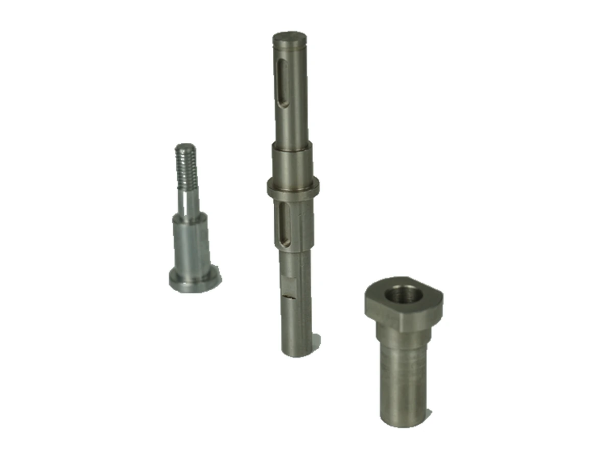
Drawing-defined shafts with longitudinal spline teeth, stepped journals and end features. Review the mating spline, engagement length, datums and inspection requirements together.
Upload CAD Drawings for a Quote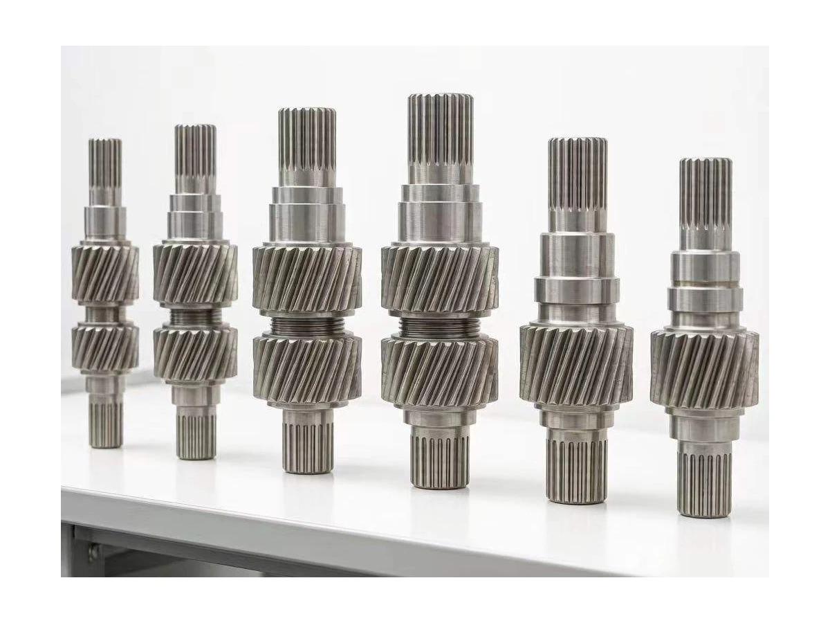
Specify the tooth form, tooth count and governing drawing or standard. An outside diameter alone does not define the mating spline.
Define the usable engagement length, tooth runout and shoulder positions. Allow clearance where the mating hub meets a shoulder or relief.
Relate splined sections to bearing journals and other rotational features. State the surfaces used to establish the functional datum axis.
Show threads, grooves and end holes needed for retention. Keep their locations clear of the working engagement region.
Review the spline generation method alongside turned journals, shoulders and secondary features. Tool access, tooth form and material condition determine whether the proposed geometry can be produced and measured; the process route requires drawing review.
Consider corrosion exposure and the condition of spline and journal surfaces. Specify any finishing requirement at the mating teeth.
Review tooth contact, strength and the requested heat-treatment condition. Identify dimensions that must be assessed after treatment.
Evaluate weight and stiffness against the actual contact duty. Any surface treatment must be included in the spline-fit review.
Use only where the mating design and duty justify the alloy. Confirm tooth geometry, wear requirements and final surface condition.
These grades are engineering selection candidates, not a statement of stock availability or verified capability for every material condition. Material, heat treatment and inspection requirements are subject to factory confirmation against the drawing.
Explore CNC Metals & MaterialsUse the dimensioned drawing to define these requirements. Photographs illustrate visible geometry; they do not establish a standard size, material grade or performance rating.
A splined interface transfers rotation between a shaft and a matching hub. Procurement needs the paired profile definition, engagement length and any axial movement requirement.
Some assemblies combine splined engagement with axial travel. Define the sliding fit, alignment and lubrication requirements rather than assuming all splines can slide under load.
A replacement must match the existing mating component as well as the shaft envelope. Provide the original interface drawing or agreed measurement requirements before selecting a production route.
Review tooth termination near shoulders and the clearance available for tooling. Full-depth teeth cannot be assumed to end against a sharp wall.
Identify material condition and treatment stages before setting final acceptance requirements. Review how those stages affect tooth and journal geometry.
Supply the hub specification and required fit. A generic shaft photograph does not define backlash or load capacity.
Agree which dimensions need records and whether the specified acceptance method is available. Functional gauges and special measurements require confirmation.
Send the CAD model and project requirements for manufacturing review.
Upload CAD Drawings for a Quote