Stepped Profiles
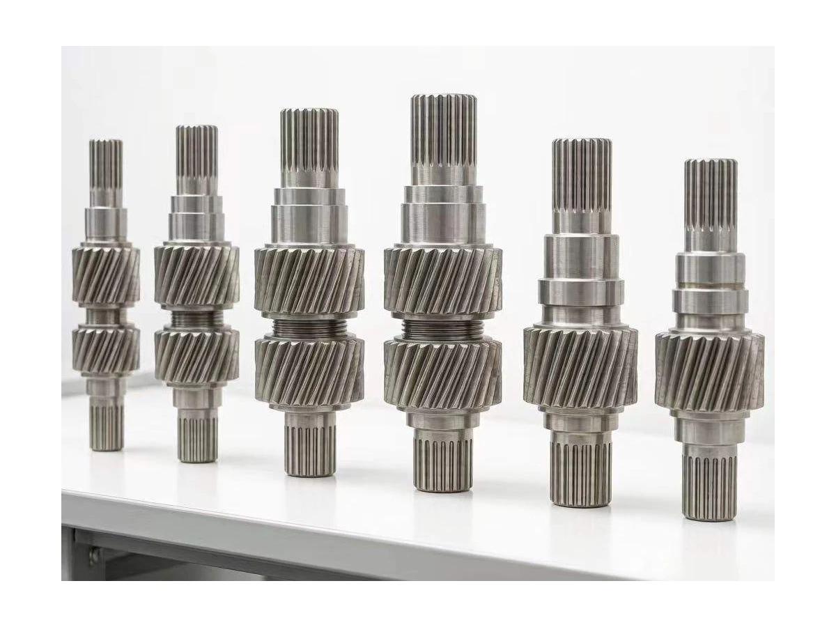
Distinct diameters and shoulders locate bearings, spacers or other mating parts along the shaft. Dimension axial positions from functional datums so the assembly stack can be reviewed without ambiguous chained dimensions.
Custom stepped shafts with machined diameters, shoulders and secondary features. Review critical dimensions, materials and inspection needs for your drawing.
Upload CAD Drawings for a Quote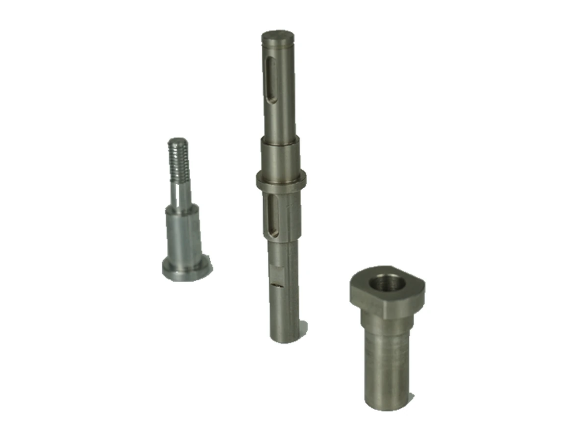
Distinct diameters and shoulders locate bearings, spacers or other mating parts along the shaft. Dimension axial positions from functional datums so the assembly stack can be reviewed without ambiguous chained dimensions.
Bearing seats, slots, flats and threads serve different mating functions. Identify which surfaces carry fits, transmit rotation or retain components, and include the relevant mating-part information.
The CAD model defines shape while the drawing defines controlled dimensions and acceptance criteria. Keep revisions aligned and state the material condition and finishing sequence that affect the final interfaces.
Identify critical diameters and their relationship to the chosen datum axis. Specify required records and accessible inspection surfaces so the measurement approach can be reviewed before manufacture.
CNC turning establishes rotational features; milling and drilling address slots, flats, holes and secondary geometry. Review the material condition, machining sequence and finishing requirements together so critical interfaces are specified in their final state.
Review corrosion exposure, mating-surface requirements and material condition together. Define the finish and any post-machining treatment so the functional diameters can be assessed in their final state.
Consider strength, wear and the required heat-treatment condition alongside shaft fits. State whether critical diameters are controlled before or after treatment, and identify the surfaces requiring final inspection.
Balance weight and stiffness against the interface and loading conditions. Confirm alloy, temper and anodizing requirements, including whether functional fits need masking or allowance for the finished surface.
Review machinability, threaded connections and functional contact interfaces. Specify the alloy and service environment rather than selecting material from the appearance of a reference photograph.
These grades are engineering selection candidates, not a statement of stock availability or verified capability for every material condition. Material, heat treatment and inspection requirements are subject to factory confirmation against the drawing.
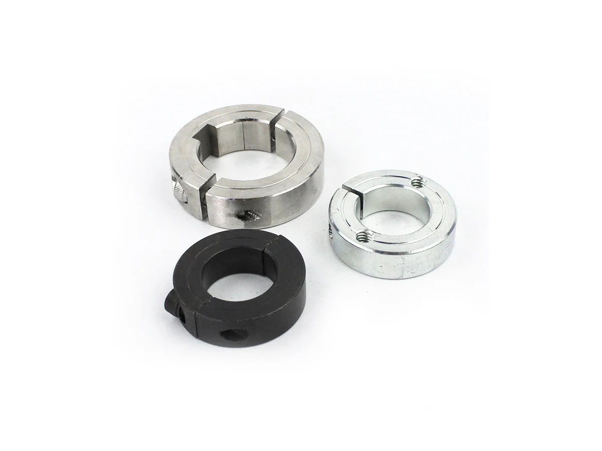
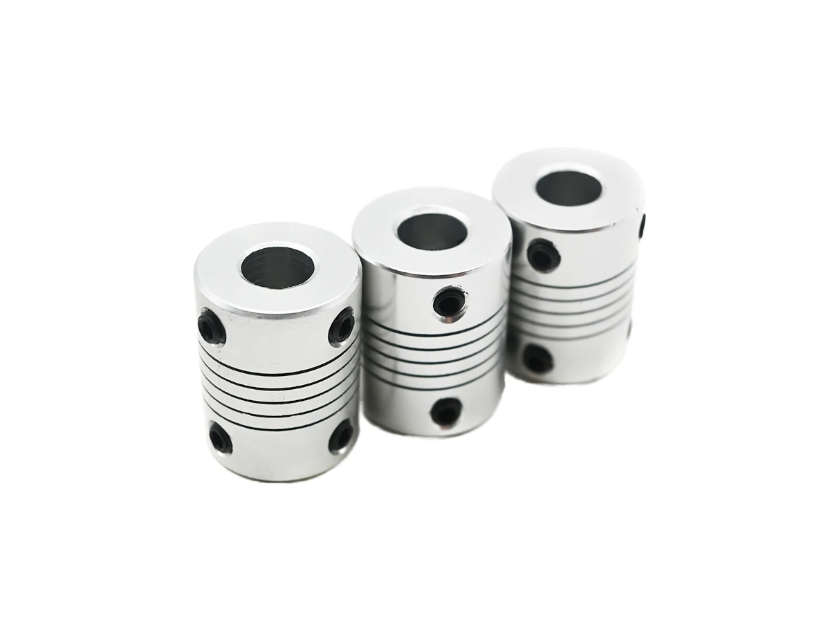
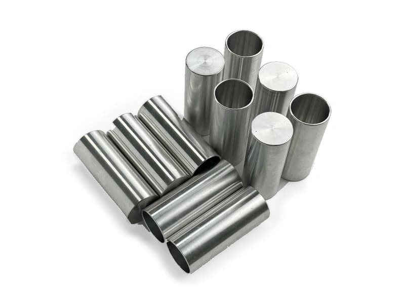
Explore CNC Metals & MaterialsUse the dimensioned drawing to define these requirements. The photographs show real component geometry; they do not establish a standard size, material grade or tolerance.
Stepped shafts position bearings, spacers and drive elements within a rotating assembly. Shoulder spacing controls the axial stack, while shaft diameters and datum-axis relationships govern the mating interfaces. Procurement drawings should identify controlled fits, retention features and the surfaces used for runout inspection.
Drive and positioning mechanisms may combine shaft journals with flats, slots or threaded ends for connected components. The assembly design should define how these features align with bearings, couplings and mounting structures. Buyers should provide mating-part requirements and confirm which dimensions remain critical after finishing or treatment.
Locating and rotating shaft elements establish repeatable positions within jigs, development assemblies and test mechanisms. Steps and reference diameters determine seating and alignment relative to the fixture. The RFQ should identify the datum scheme, replaceable interfaces and inspection evidence needed to accept the part.
Review deep reliefs, narrow grooves and shoulder radii against tool access and mating clearances. Distinguish functional undercuts from optional edge treatment so the machining sequence can be planned around the actual assembly need.
Long, slender or interrupted sections may need additional support and a staged machining sequence. Identify the surfaces that can be held and any areas that must remain free of workholding marks.
Define fits in the final material and surface condition, including any heat treatment or coating. Clarify masking, allowances and post-treatment checks for interfaces that cannot be accepted solely from pre-finish dimensions.
Specify critical characteristics, datum setup and required records before manufacture. Review measurement access, sampling and the relationship between separately machined features rather than relying only on individual diameter checks.
Send the CAD model and project requirements for manufacturing review.
Upload CAD Drawings for a Quote