Bore & Shaft Fit
Define bore size and the mating shaft condition. Clearance and surface requirements depend on the retention design.
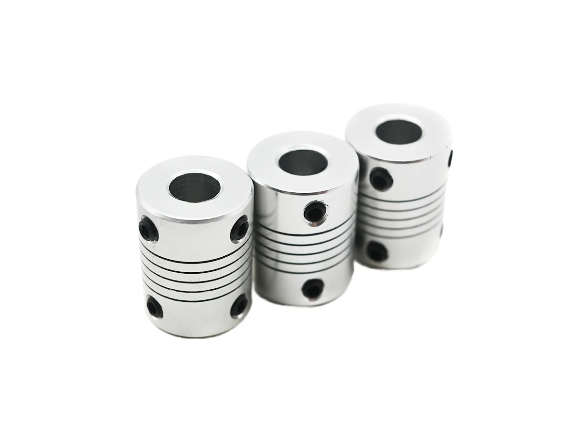
Split-clamp and drawing-defined shaft collars with controlled bores, faces and fastening features. Review axial location, shaft condition and the selected retention method.
Upload CAD Drawings for a Quote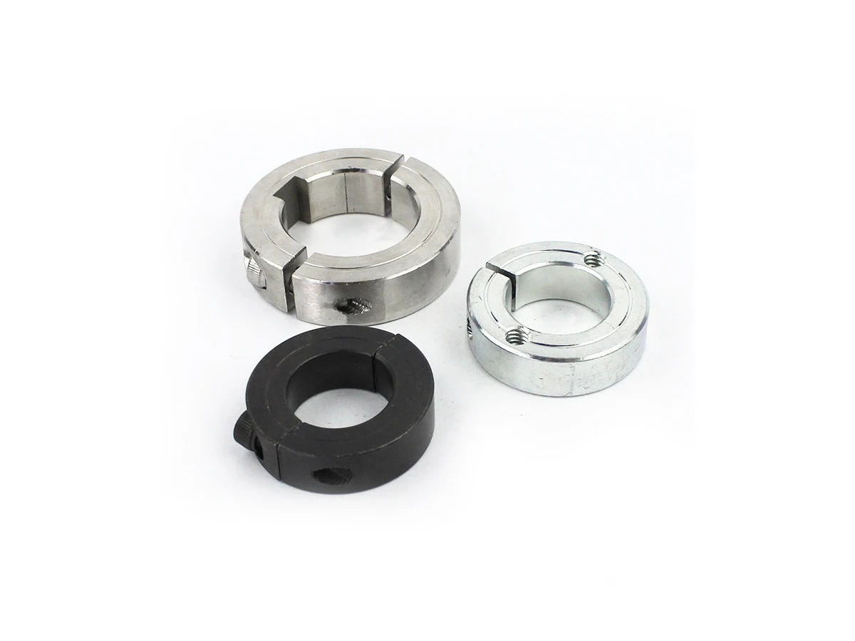
Define bore size and the mating shaft condition. Clearance and surface requirements depend on the retention design.
Specify one-piece or split construction, gaps and screw interfaces. Do not replace a clamp design with a plain ring or bushing.
Use collar faces to define the intended assembly position. State the relationship between the working face and shaft bore.
Include screw size, engagement and installation clearance. Hardware and assembly requirements should be defined alongside the collar geometry.
Review the bore, split and fastening sequence together so the required assembled condition is understood. Clamping gaps, screw access and working-face requirements affect both fixturing and inspection.
Consider corrosion exposure and the required bore finish. Confirm fastener compatibility and the condition of the assembled working faces.
Review strength, surface treatment and shaft contact conditions. Define final bore and face requirements after finishing.
Consider weight and the clamp section around fastening holes. Include anodizing allowances at controlled mating surfaces where applicable.
Use where the drawing and operating conditions support the material choice. Review thread engagement and contact duty before manufacture.
These grades are engineering selection candidates, not a statement of stock availability or verified capability for every material condition. Material, heat treatment and inspection requirements are subject to factory confirmation against the drawing.
Explore CNC Metals & MaterialsUse the dimensioned drawing to define these requirements. Photographs illustrate visible geometry; they do not establish a standard size, material grade or performance rating.
A collar can locate components or limit movement on a shaft. The required holding condition depends on shaft surface, collar design and assembly, so it must be specified separately.
Working faces can establish spacing around bearings, rollers or other components. Review face alignment and access before selecting the collar envelope.
Collars may allow repositioning during fixture setup. Procurement should define how the collar is secured and distinguish dimensional checks from holding-force tests.
Agree whether bore acceptance is assessed before or after assembly. The clamp gap and screw condition are relevant to the measurement.
Identify matching requirements for split constructions. Keep paired features and revision control clear on the drawings.
Review the shaft entry, split and screw breakouts. Edge treatment must not damage a required working face.
Define any required retention or assembly test explicitly. No axial holding capacity is assumed from the photo or material choice.
Send the CAD model and project requirements for manufacturing review.
Upload CAD Drawings for a Quote