Internal Thread Definition
State the thread form, hand, pitch, lead and number of starts. A generic tapped hole is not a complete lead-screw nut specification.
Drawing-defined nuts for matched lead-screw assemblies. Review the internal thread, screw pairing, mounting geometry and motion requirements before selecting materials or manufacturing methods.
Upload CAD Drawings for a Quote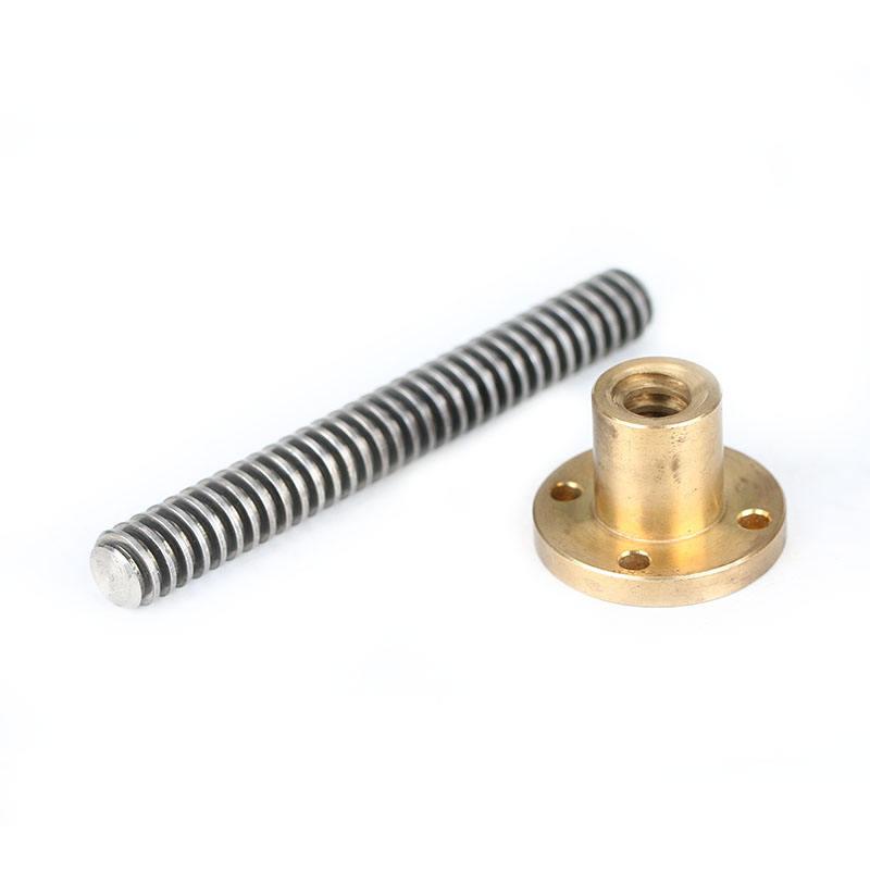
State the thread form, hand, pitch, lead and number of starts. A generic tapped hole is not a complete lead-screw nut specification.
Provide the mating screw drawing or interface specification. Define clearance or backlash requirements for the pair rather than for the nut alone.
Locate flanges, fixing holes and external datums relative to the thread axis. Include access for assembly and any retaining hardware.
Define travel, duty, environment and lubrication requirements. Material selection must consider the complete sliding interface.
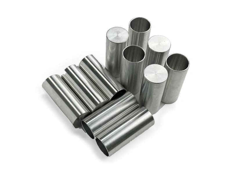
Review access to the internal thread, usable engagement and mounting features before proposing a process. Thread verification needs to match the specified screw interface; neither a plain sleeve photograph nor a standard tapped part establishes this geometry.
Review machinability together with the screw material and contact duty. Confirm wear, lubrication and finished thread requirements.
Consider the proposed screw pairing and sliding service. The exact alloy and availability require factory confirmation.
Review temperature, moisture, loading and dimensional behaviour for the actual mechanism. No dry-running life is assumed.
Treat these as drawing-dependent candidates. Assess the matched materials, treatment and lubrication before accepting a thread design.
These grades are engineering selection candidates, not a statement of stock availability or verified capability for every material condition. Material, heat treatment and inspection requirements are subject to factory confirmation against the drawing.
Explore CNC Metals & MaterialsUse the dimensioned drawing to define these requirements. Photographs illustrate visible geometry; they do not establish a standard size, material grade or performance rating.
A screw and nut pair converts relative rotation into linear movement. Mounting alignment, thread clearance and the intended duty must be considered together.
A lead-screw nut can form part of a manually or mechanically adjusted assembly. Define retention, travel and required positioning behaviour before selecting the thread and material.
Development fixtures may use screw-driven movement for setup or positioning. Buyers should provide the mating screw and distinguish dimensional inspection from motion or load testing.
Review blind-end clearance, relief and thread termination. The usable engagement may differ from the overall nut length.
Confirm the complete thread designation and mating part. Do not substitute a general-purpose thread for a specified motion interface.
Review service conditions and the selected materials as a pair. Wear and service life require validation beyond dimensional manufacture.
State the required assembled condition and measurement method. No anti-backlash mechanism or positioning accuracy is implied unless it is defined and verified.
Send the CAD model and project requirements for manufacturing review.
Upload CAD Drawings for a Quote