Tooth Geometry
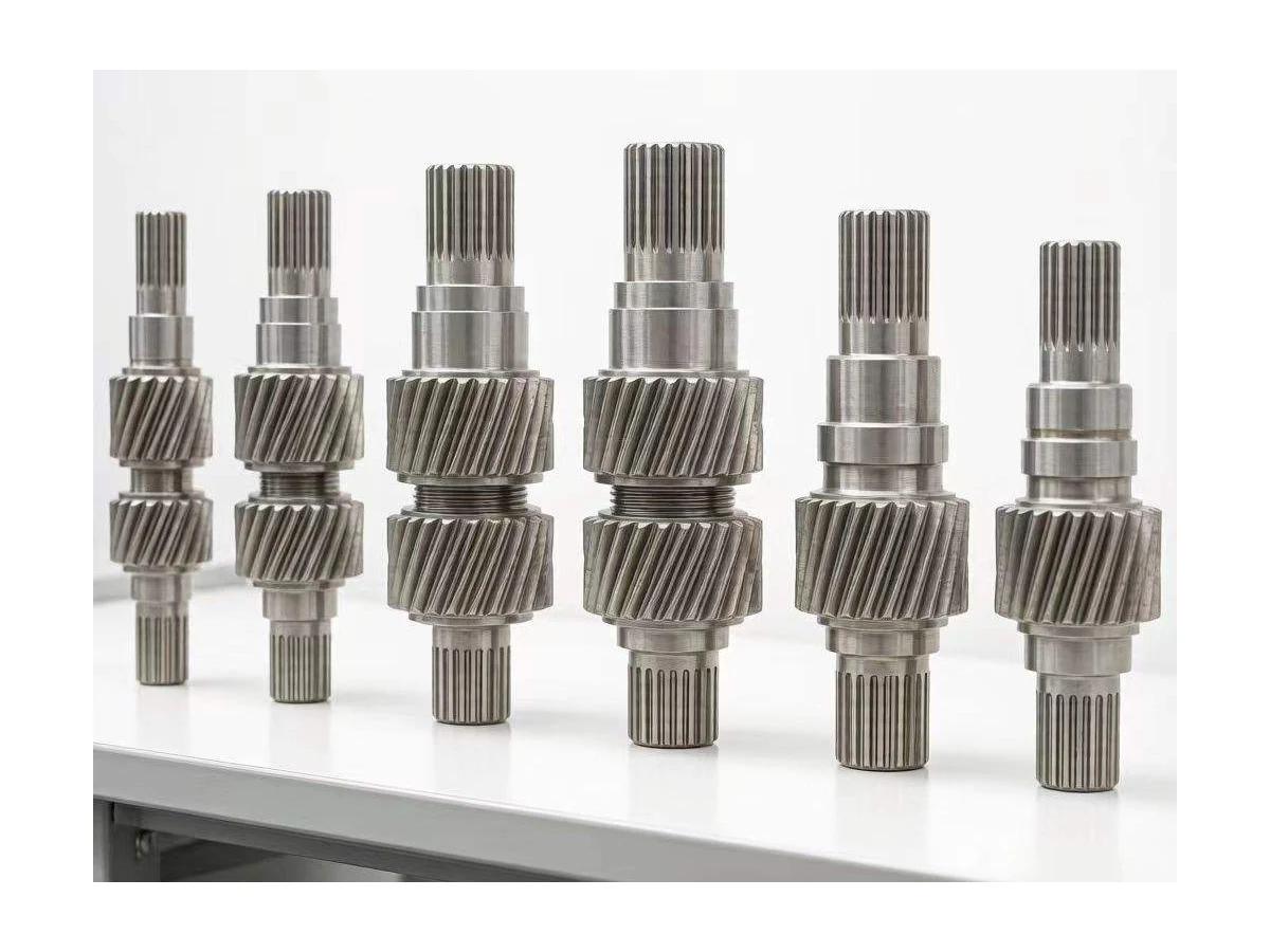
Define tooth count, pitch or module and pressure angle. Include helix and profile information where the design requires it.
Drawing-based toothed components with defined bores, hubs and mounting features. Review tooth geometry, the mating gear and assembly requirements before manufacture.
Upload CAD Drawings for a Quote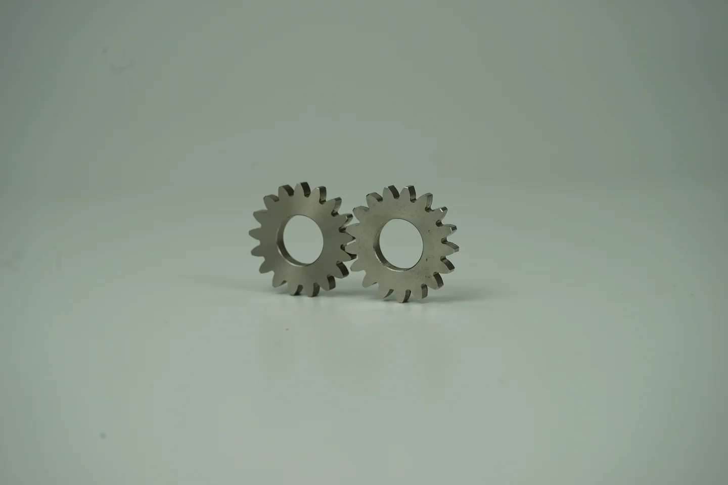
Define tooth count, pitch or module and pressure angle. Include helix and profile information where the design requires it.
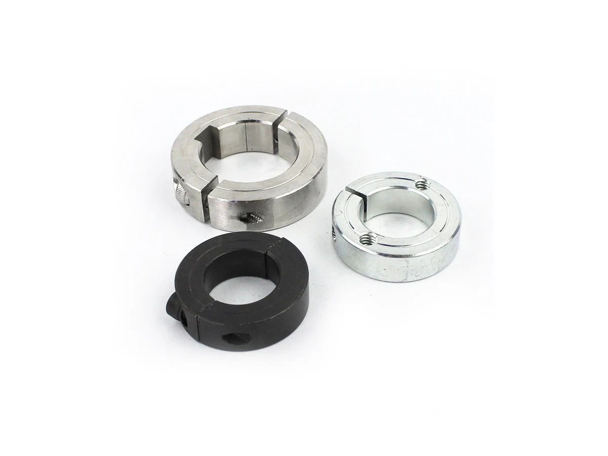
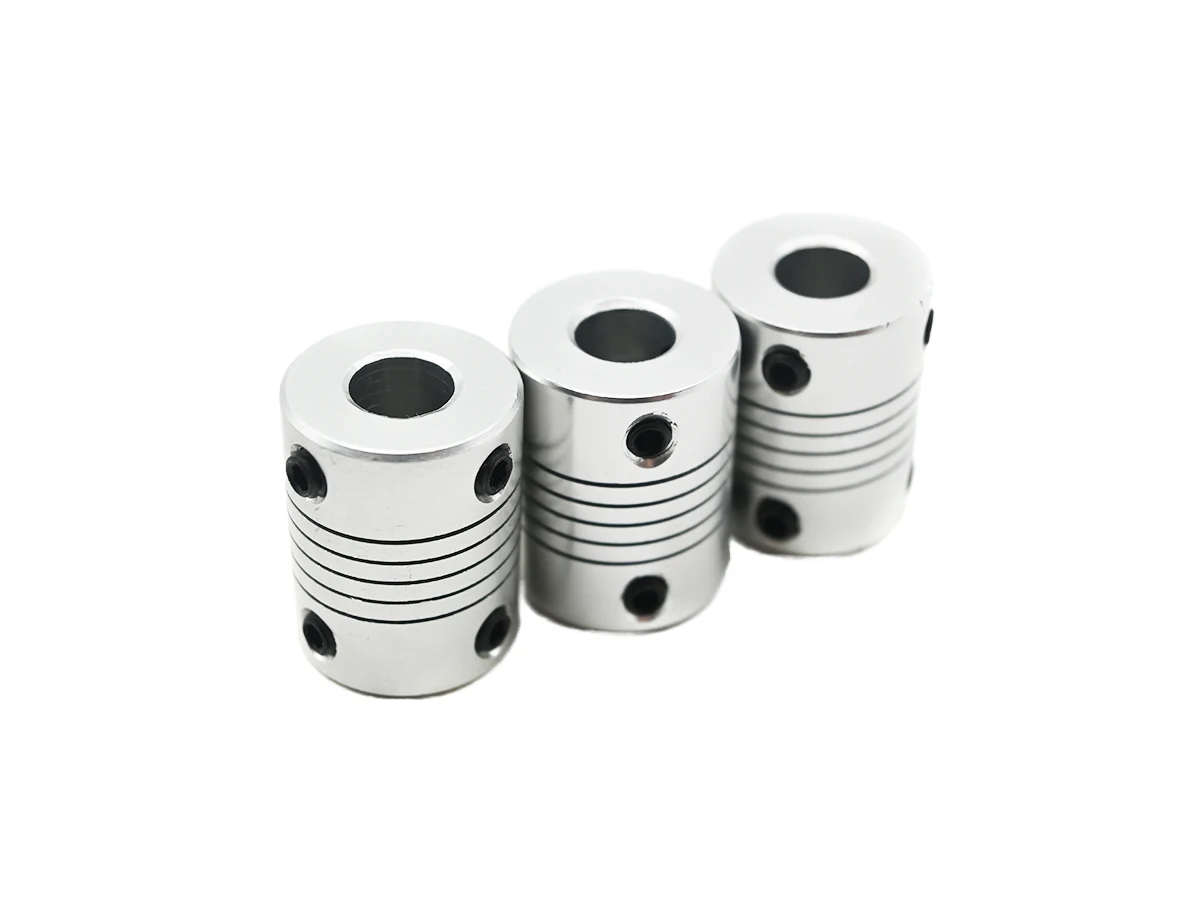
Bores, keyways and fixing holes connect the gear to its shaft. Relate these features to the working tooth geometry and assembly datums.
Specify the mating gear and operating arrangement. Backlash and tooth contact are assembly requirements, not dimensions inferred from a product photo.
Keep the tooth specification, CAD model and drawing at the same revision. Identify any inspection or finishing requirements that affect acceptance.
Review tooth generation separately from blank turning, bore machining and hub features. Tooth form, material condition and inspection requirements determine the proposed process route; no gear grade or load rating is assumed.
Review the service environment together with tooth contact and wear requirements. Specify material condition and any final treatment.
Identify required strength, wear behaviour and heat treatment on the drawing. Agree the sequence for final bore and tooth inspection.
Assess weight and contact duty against the gear design. Coating thickness and final bore dimensions need a defined relationship.
Consider machinability and the mating material for the intended mechanism. Confirm wear and lubrication requirements for the actual duty.
These grades are engineering selection candidates, not a statement of stock availability or verified capability for every material condition. Material, heat treatment and inspection requirements are subject to factory confirmation against the drawing.
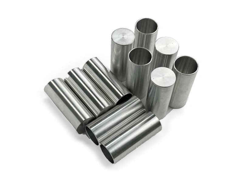
Explore CNC Metals & MaterialsUse the dimensioned drawing to define these requirements. Photographs illustrate visible geometry; they do not establish a standard size, material grade or performance rating.
Meshing gears transfer motion between shafts. The buyer should define the mating pair, tooth specification and mounting arrangement rather than selecting only by outside size.
A toothed component may support controlled rotation or indexing. Positioning requirements depend on the complete mechanism, including clearance, support and drive control.
Development assemblies may need revised bores, hubs or face widths around a tooth design. Keep those changes linked to the tooth specification and the required fit checks.
Avoid defining a gear solely with a simplified CAD tooth pattern. Include the governing tooth specification and acceptance criteria.
Check tool and assembly access around hubs, keyways and shoulders. Review internal corners and reliefs before manufacture.
Review material treatment and finishing before final dimensions are set. Identify which interfaces require inspection in the finished state.
Provide mating gear and shaft information. Gear noise, life and load capacity require design evaluation beyond the visible geometry.
Send the CAD model and project requirements for manufacturing review.
Upload CAD Drawings for a Quote