Machined Geometry
Slotted coupling components combine axial bores, fixing details and segmented interfaces.
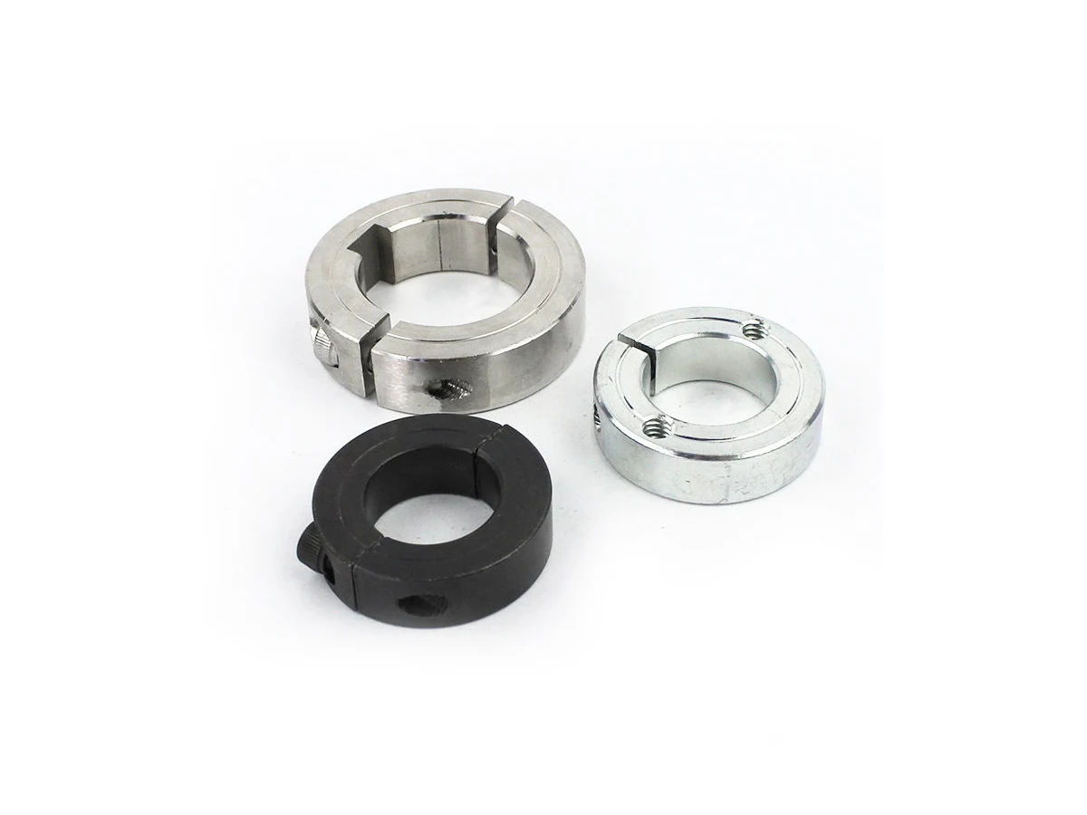
Cylindrical coupling components with slotted or segmented interfaces, axial bores and fixing details. Define the mating geometry and retention arrangement for this component style.
Upload CAD Drawings for a Quote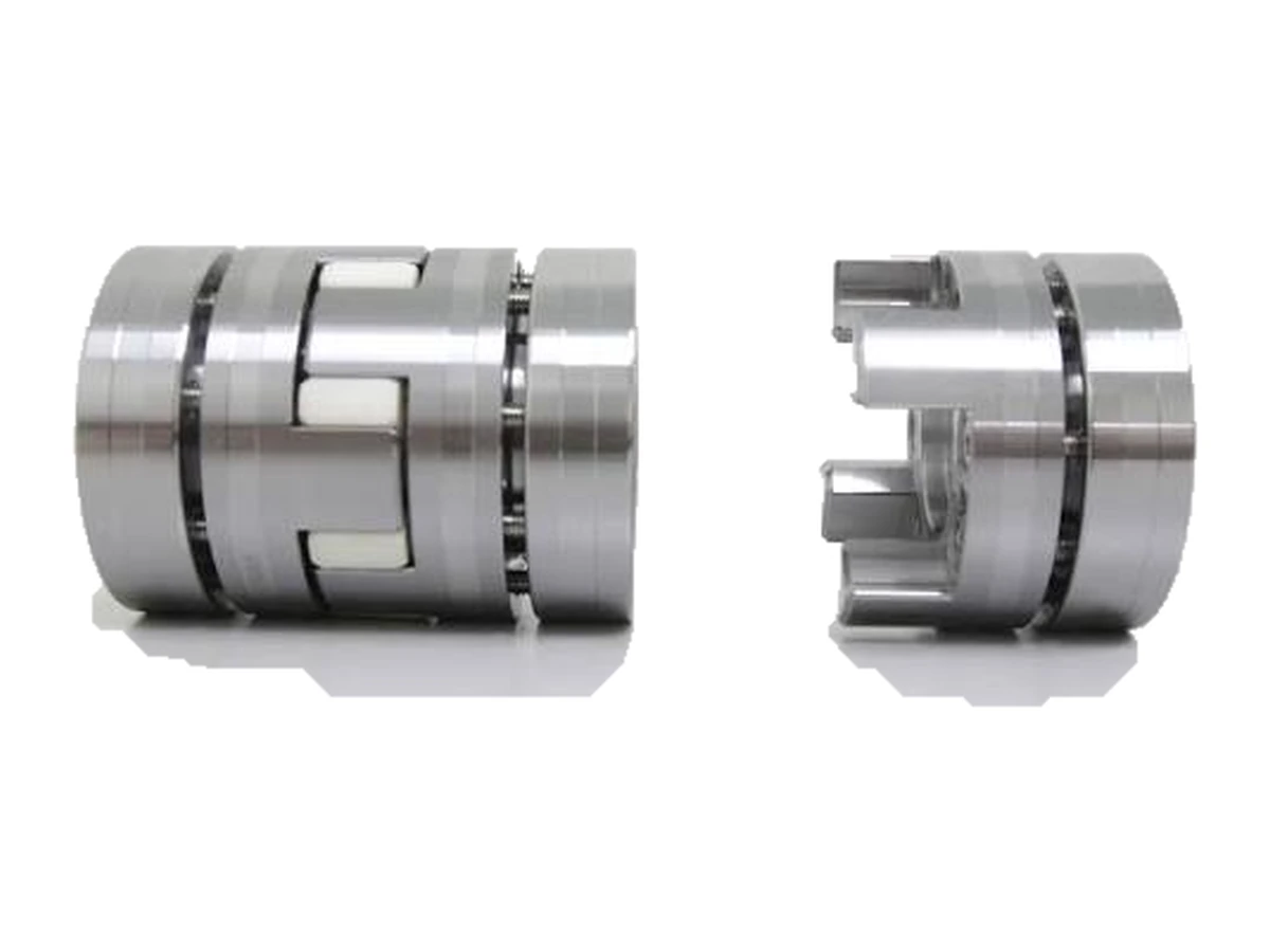
Slotted coupling components combine axial bores, fixing details and segmented interfaces.
Define both shaft interfaces and assembly clearances; allowable movement requires design review.
Specify the segmented interface and how it engages the mating component. Include axial location and retention details.
Relate slots and fastening features to the bore axis. Review assembly clearance at the interrupted surfaces.
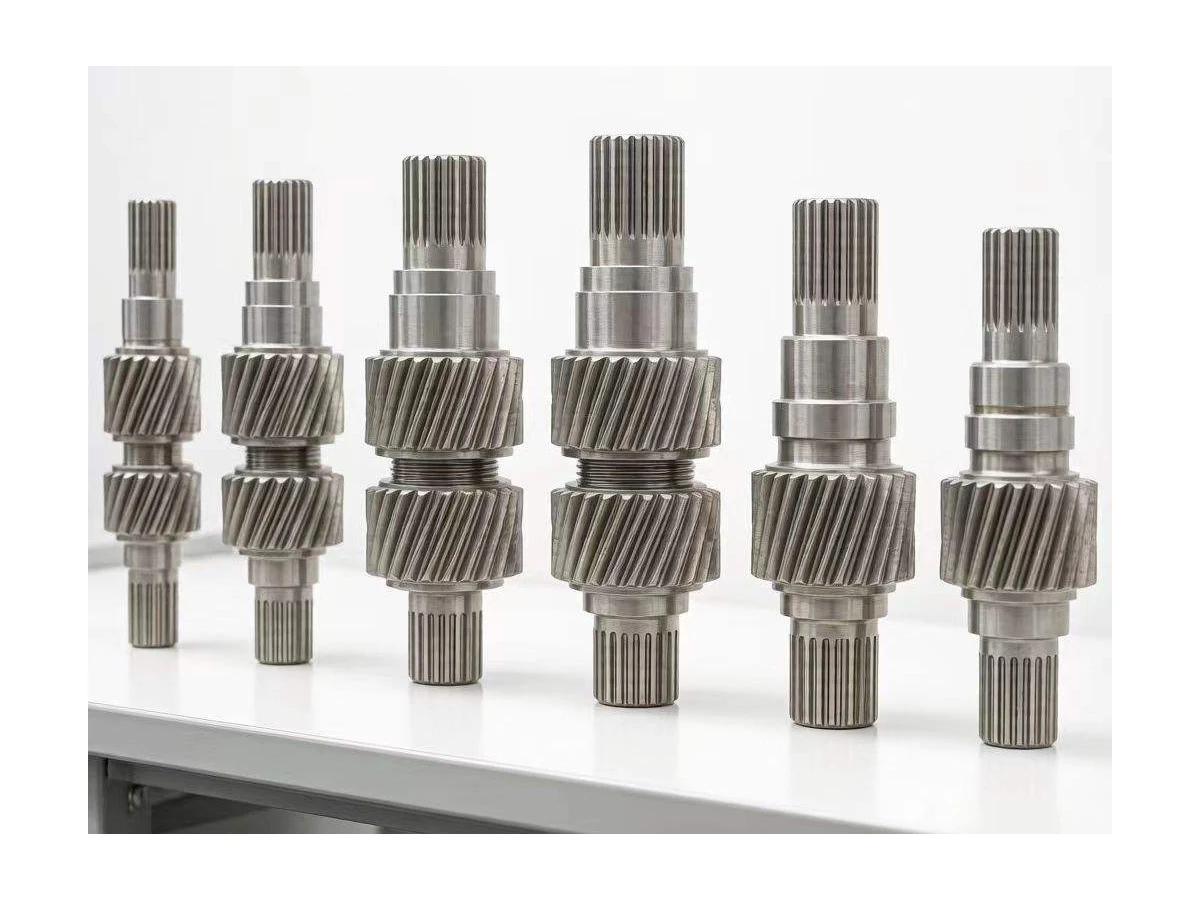
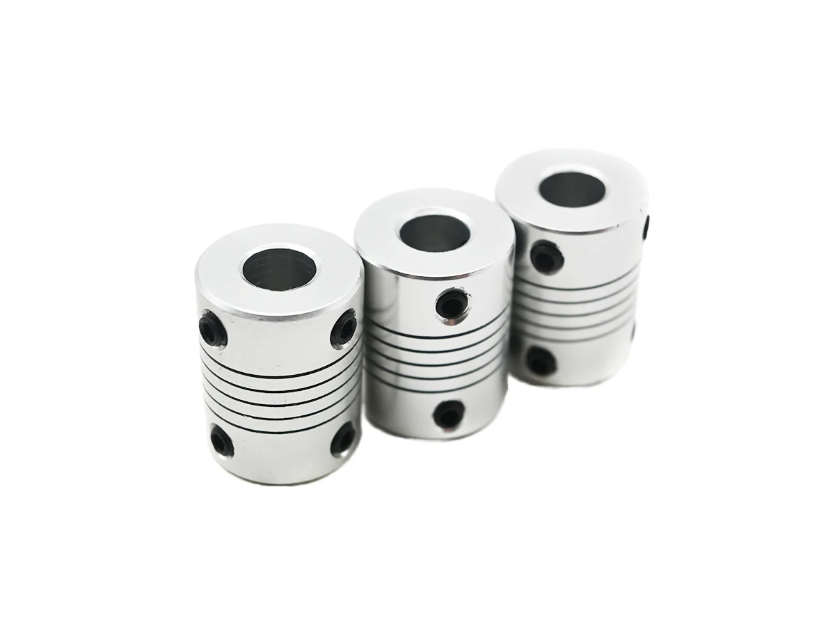
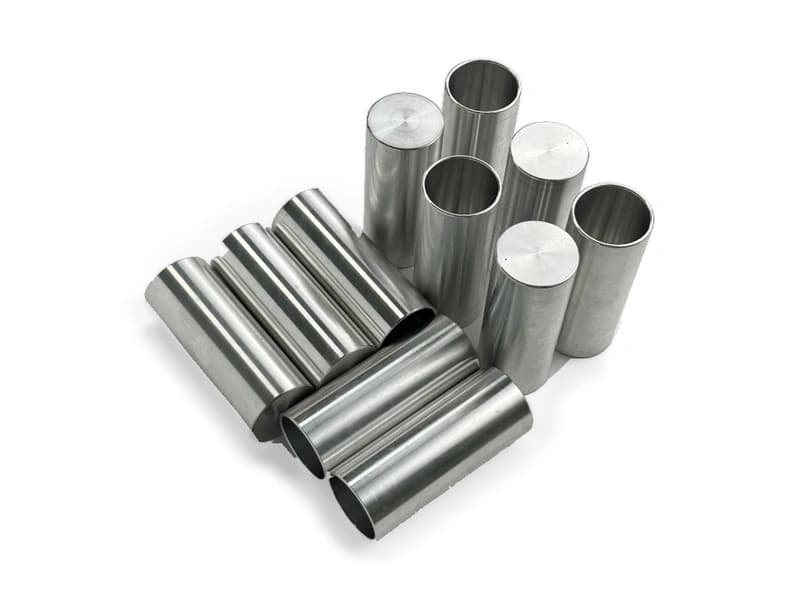
Review turned bores and outer profiles alongside milled slots and fixing features. These photographed components are distinct from the helical-slot flexible couplings shown elsewhere; operating behaviour must come from the actual design.
For coupling components, specify the alloy, condition and finish on the drawing. Review the finished interfaces, treatment sequence and inspection requirements before selecting this candidate material.
For coupling components, specify the alloy, condition and finish on the drawing. Review the finished interfaces, treatment sequence and inspection requirements before selecting this candidate material.
For coupling components, specify the alloy, condition and finish on the drawing. Review the finished interfaces, treatment sequence and inspection requirements before selecting this candidate material.
For coupling components, specify the alloy, condition and finish on the drawing. Review the finished interfaces, treatment sequence and inspection requirements before selecting this candidate material.
These grades are engineering selection candidates, not a statement of stock availability or verified capability for every material condition. Material, heat treatment and inspection requirements are subject to factory confirmation against the drawing.
Explore CNC Metals & MaterialsUse the dimensioned drawing to define these requirements. Photographs illustrate visible geometry; they do not establish a standard size, material grade or performance rating.
A coupling component may connect mating shaft or hub features. Supply the complete interface geometry and retention method for review.
Compact coupling parts can sit close to bearings or surrounding structure. Review axial assembly access and the operating envelope.
Development parts can test fit and installation sequence. Torque capacity, flexibility and alignment limits require separate design validation.
Keep the bore axis and mating-segment datums explicit throughout turning and milling.
Review slot width, end radii and access to internal fixing details.
Specify the final contact surfaces and remove burrs without rounding controlled interfaces.
Agree bore and mating-profile inspection separately from functional operating tests.
Send the CAD model and project requirements for manufacturing review.
Upload CAD Drawings for a Quote