
Making one CNC prototype does not automatically mean that 50 copies will assemble and function consistently. As a hardware team moves from functional validation to a small production run, the question changes from “Can this part be machined?” to “Can the critical fits, datums and costs be controlled across the batch?”
Actuator housings, stepped shafts, dowel pins and liquid cold plates serve different functions. What they share is the need to distinguish genuinely critical features from dimensions that do not control the product’s performance. This guide uses four groups of custom CNC parts—Structural & Housings, Motion & Transmission, Precision Fasteners, and Thermal & Tooling—to explain DFM decisions, manufacturing routes, inspection needs and the path from a first prototype to repeat orders.
When should you choose CNC instead of 3D printing or production tooling?
For functional prototypes and low-volume projects, CNC machining can use production-relevant metals and engineering plastics while controlling mating faces, bores, shaft diameters, mounting datums and surface finishes. It usually avoids the need for a full injection or die-casting tool when the drawing is still changing.
That does not make CNC the only or automatically best choice for every 1–100-part project. Geometry, selected material, intended function, quantities, tolerance requirements, lead time and total budget all matter.
| Process | Often a good fit for | What to review for small batches |
|---|---|---|
| CNC machining | Loaded structures, controlled bores and shafts, mounting datums, metal or engineering-plastic functional parts | Programming, setups, deep cavities, multi-face access and inspection add cost; very tight tolerances need a drawing review |
| 3D printing | Complex internal passages, topology-led geometry, quick appearance evaluation and some functional prototypes | Mechanical properties, accuracy and surface quality depend on process and material; precision mating faces may need machining |
| Injection molding | Stable plastic designs with enough repeat demand to justify tooling | Mold cost, lead time and changes to the design can dominate early project economics |
| Die casting | Repeat metal components in suitable casting alloys | Tooling, draft angles, porosity risks and post-machining needs must be assessed against the geometry and volume |
For one or two appearance samples, additive manufacturing may be more economical. For a functional test that depends on real stock material, controlled fits and repeatable dimensions, CNC is often a better route. Once the order grows, compare the per-batch cost of programming, fixtures and inspection against alternative processes again.
Before requesting a quote, ask three questions: What function does the part perform? Which features actually need close control? And how many pieces might be needed after the first validation—and how likely is the drawing to change? Those answers make both DFM and pricing more useful.
Structural & Housings: datums, assembly fit and distortion
Typical components include actuator housings, enclosure bezels, motor mount brackets, bearing blocks, bearing housings and flanges. These components often combine mounting planes, locating shoulders, hole patterns and deep pockets or thin walls.
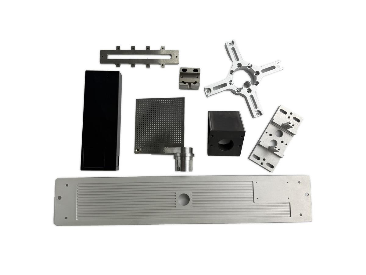
A single bore can meet its diameter tolerance and still assemble poorly if its position relative to the mounting datum is wrong. Material stress released during machining may also shift thin walls or housing faces after the part leaves the fixture.
Separate roughing from finishing when distortion is a concern
For an aluminum housing with substantial material removal, a suitable plan may rough-machine the blank first, assess material movement and then finish the critical faces. Depending on stock condition, geometry and schedule, an intermediate rest period or stress-relief step may be considered. Low-force tool paths, staged removal from opposite sides and temporary supports can reduce risk in slender regions.
These measures are not a universal, fixed sequence. Finishing allowance and any stress treatment need to be chosen from wall thickness, pocket depth, material condition and actual machining trials—not a blanket rule that every housing needs the same stock allowance.
Use the same functional references in the drawing, machine setup and inspection
For a motor-mount bracket, the important relationship may be between its base, locating register, bearing bore and bolt pattern. The drawing should define primary and secondary datums and specify flatness, perpendicularity or true position where those characteristics affect assembly.
Three-axis, indexed 3+2 and five-axis machining may all be appropriate. Reducing re-clamping can lower positioning risk, but a five-axis machine does not automatically machine every feature in one setup. A CMM or other dimensional check should follow the design datum structure instead of reporting only unrelated single dimensions.
Define acceptance criteria before ordering 10–50 parts
Confirm the critical mounting faces, fit bores and locating shoulders, whether they need inspection before and after finishing, and whether a trial assembly with mating parts is required. For deep pockets, thin walls and tight internal corners, request DFM feedback on tool reach, corner radius, deflection and fixturing before the batch begins.
A related engineering example is covered in our CNC aluminum housing DFM guide.
Motion & Transmission: functional axes, runout and fit
Typical parts include splined and stepped shafts, gears, flexible couplings, lead screw nuts and shaft collars. Their dimensions must be considered in the context of rotation, loading and mating components—not only as separate measurements on a print.
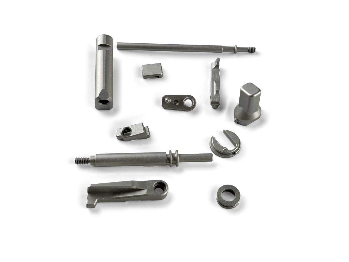
Two shaft journals may individually measure within size limits while the assembled rotor still exhibits unacceptable runout. Define relationships to the functional rotation axis, bearing seats, surface finish, loading conditions and speed before quoting the process.
Turn-mill planning can reduce datum transfers
Parts with shoulders, outside diameters, threads and end-face relationships may suit a turning-led route. When they also need cross-holes, D-cut flats, keyways or multiple angular features, live tooling and C-axis turn-mill machining can sometimes complete more features with fewer setups.
The achievable result depends on machine configuration, length-to-diameter ratio, chucking stiffness, tools and metrology. Long, thin shafts also require attention to support, bending and vibration. If a very tight runout or positional requirement is essential, identify it as a critical feature and agree how it will be measured.
Cross-holes and keyways introduce edge-quality risks
Where drilled passages intersect a shaft bore, inaccessible burrs can remain. Flats and keyways also need orientation and position control relative to the rotation axis. Along with dimensional limits, specify which edges must be deburred, whether sharp edges are allowed, and whether a bearing or seal must pass over the feature during assembly.
Rather than assume every cross-hole can hold the same micrometer-level positional tolerance, review hole depth-to-diameter ratio, tool access, datum selection and inspection capability. A first-article fit test may reveal concerns that a simple diameter reading will miss.
For splines and gears, compare processes before selecting one
Low quantities of non-standard tooth forms may justify comparing hobbing, shaping, gear milling or wire EDM. Wire EDM can work for certain electrically conductive profiles that are accessible through the cutting direction, but not every three-dimensional tooth surface is suitable. It is not necessarily faster or cheaper than standard tooling already available.
A useful RFQ includes module or tooth geometry, mating part details, heat-treatment condition, surface quality and an acceptance method for the mesh or transmission function. A label such as “IT7” alone is not an adequate substitute for those functional requirements.
Precision Fasteners: specify the mating fit, not just the pin size
Typical parts include custom dowel pins and bushings, drill bushings, standoff spacers and threaded inserts. Standard catalog parts should usually be considered first. Custom CNC manufacturing becomes more useful when the length, step geometry, material, corrosion requirement or installation envelope is unusual.
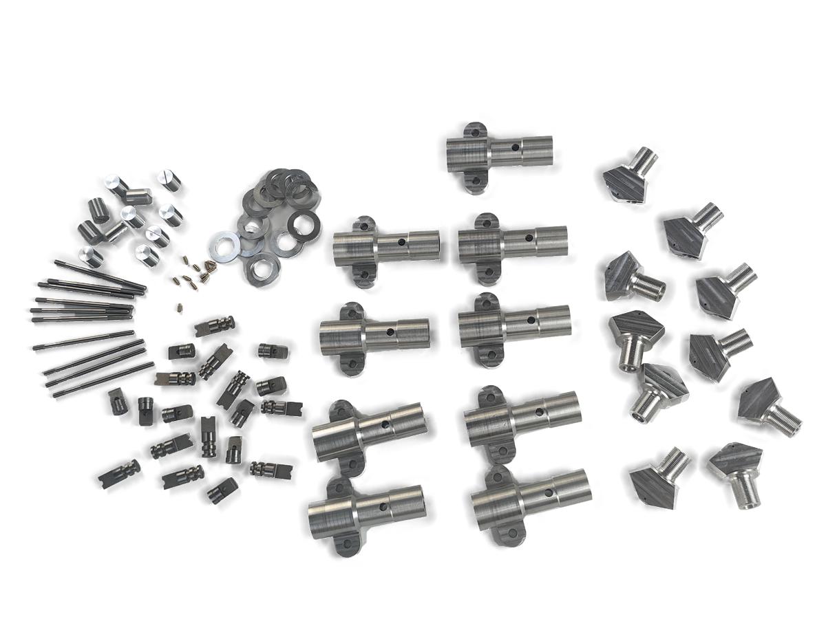
A pin diameter meeting its own print tolerance does not prove that the pin-and-hole pair gives the intended fit. The interaction between the two components matters.
Choose a clearance, transition or interference fit before selecting the tolerances
Fit selection depends on installation and removal frequency, load, temperature, materials and the hole-making process. An H7 hole with a particular shaft tolerance zone must be evaluated as a specific combination; H7/k6 and H7/m6, for example, cannot be treated as interchangeable shorthand for one universal result.
Where press fitting is intended, specify lead-in chamfers, deburring, surface condition, the assembly method and an acceptable press-force or assembly trial. Removable locating pins may instead prioritize wear, replacement and repeatable positioning.
Heat treatment and grinding are options, not mandatory steps
Hardened steel locating pins may need a sequence including heat treatment, finish turning and cylindrical grinding. Aluminum, brass or stainless components may require a different route. If a low Ra value or tight cylindricity is required, identify the measured region, inspection method and acceptance range rather than promising the same finish on every component.
Standoffs and inserts need batch-level assembly consistency
For a standoff supporting a PCB or precision sensor, the effective assembled height, face squareness and thread consistency may govern performance. Excessive height variation can introduce uneven board stress. Before a small batch is made, agree height tolerance, go/no-go thread checks, sample or 100% inspection criteria and whether a trial assembly on the actual PCB is required.
Thermal & Tooling: test fluid systems and repeatable fixtures differently
Liquid cold plates, heat sinks and manifold blocks are typically evaluated for heat transfer or flow performance. Soft jaws, welding fixtures and assembly jigs serve another purpose: repeatable clamping and assembly. They should not share one generic quality checklist simply because CNC machining is used for all of them.
Liquid cold plates and manifolds: start from the thermal and fluid requirements
Define the heat load, coolant, flow rate, inlet and outlet temperature, allowable pressure drop and available envelope before finalizing a passage design. For a cold plate that contacts a chip or power module, specify flatness and interface requirements only for the relevant contact region rather than applying an ultra-fine finish to every surface.
CNC machining can create channels, connection ports, sealing grooves, mounting holes and critical contact faces. However, deep-hole straightness, microchannel wall thickness and the material left between channels and seals require drawing-specific review. Vacuum brazing or friction-stir welding, if needed, should be evaluated separately for alloy compatibility, thickness, distortion, access and post-join inspection.
Machining a cold-plate component does not by itself establish that the supplier can perform every joining operation, pressure-leak test or thermal qualification. A responsible RFQ separates the machining scope from sealing, cleaning and verification responsibilities.
For a production-intent cold-plate batch, provide the fluid specification, operating pressure, required proof-test pressure and test method, acceptable leakage limit, cleanliness requirement and any flow-versus-pressure-drop or thermal-performance report. Test factors, hold times and pass/fail limits must come from project requirements and applicable standards—not a generic promise of zero leakage.
Heat sinks: evaluate the whole system, not just surface area
Heat-sink cost and function depend on material, fin geometry, airflow, attachment method and finishing. CNC prototypes can be a flexible choice when validating packaging, heat-source location or duct fit before hard tooling. Final heat performance must still be tested under the specified power, air-flow and ambient conditions.
Soft jaws, welding fixtures and assembly jigs: control repeatability before the batch
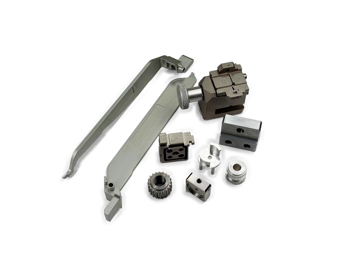
For a run of about 20–100 units, one important cost decision is whether a temporary setup is sufficient or whether purpose-built fixturing is justified. Soft jaws can conform to unusual part geometry and reduce marking. Welding fixtures must consider heat distortion, shrinkage, locator positions and welding access. Assembly jigs should reflect assembly sequence and repeat placement.
Supply the mating components, locating references, loading and unloading frequency, and acceptable repeat-location variation. A simple stop block, standard vise and replaceable soft jaw can sometimes meet the requirement more efficiently than a complex dedicated fixture.
From one prototype to 10, 50 or 100 parts: what changes?
More quantity does not simply mean “make identical copies.” It changes the need for design freeze, first-article approval, consistent fixturing, inspection records, revision traceability and repeat-order planning.
| Example quantity | Primary decision | Manufacturing and quality information to agree |
|---|---|---|
| 1–2 functional prototypes | Validate material, assembly and operating principle | STEP model, 2D drawing, critical datums, mating conditions and initial DFM comments |
| 10-part assembly trial | Check assembly fit across several parts | First-part measurement, drawing revision, assembly feedback and necessary fit checks |
| 50-part pilot batch | Check repeatability and per-part economics | Consistent setup, key-characteristic inspection plan, batch identification and rework risk |
| 100 parts or repeat orders | Establish supply cadence and documentation | Quantity pricing, process freeze, inspection records, change control and replenishment lead times |
These quantities are planning scenarios, not fixed limits for CNC processes or HERUIYUN services. Unit cost may fall when programming and setup time can be spread across a larger batch. But custom fixtures, heat treatment, 100% inspection or unusual finishes may prevent a simple proportional price reduction.
First-article approval should answer three questions: Does the component match the current drawing? Are the critical fit features suitable for the intended function? And can later parts be made and measured against the same setup and datums? If the design changes after validation, recheck the affected features rather than merely renaming the CAD file.
Five practical factors behind CNC cost and delivery time
- Material and starting stock: unusual grades, heat-treated condition and nonstandard sizes may influence sourcing time, material waste and price.
- Geometry and setup count: deep pockets, tight inside radii, long bores, free-form outlines and multiple approach directions increase machining or fixturing work.
- Tolerance allocation: reserve tight requirements for functional mating, motion and sealing features; use suitable general tolerances where precision is not performance-critical.
- Finishing and inspection: anodizing, coatings, grinding, CMM checks, FAI documentation and assembly trials should be included or excluded explicitly in the quote.
- Quantity and drawing stability: quote the first article, pilot batch and expected replenishment separately; repeated revisions can erase economies of scale.
Ask the manufacturer to compare a quote to the current drawing with one based on accepted DFM recommendations. Relaxing a nonfunctional tolerance, simplifying a difficult inside corner or reducing re-clamping can sometimes lower total cost without compromising the product. For functional components, agree which checks and process steps cannot be skipped before negotiating the shortest lead time.
If appearance approval is the main objective rather than functional precision, consider whether vacuum casting and IML/IMD-style prototype finishes offer a more suitable way to evaluate the design before hard tooling.
CNC prototype RFQ checklist: what to send for a useful quote
A drawing-led request is more useful than a message stating only “CNC part, 50 pcs.” Send the following information together so the manufacturing team can compare realistic processes, inspectable features and batch requirements.
For moving parts, add speed, load, bearing and lubrication details. For liquid cold plates, provide heat load, flow rate, fluid, pressure and leak-test acceptance criteria. For fixtures, state the located workpiece, cycle time and repeat-clamping requirement.
Have a hybrid additive-plus-machining design? Our 3D-printed blanks and CNC machining guide explains how to plan finishing stock and stable clamping before production.
The real goal: make a validated design repeatable
Structural components call for controlled assembly datums and distortion; moving parts call for functional axes and runout; locating components call for a defined pin-and-hole fit; thermal and tooling parts call for appropriate sealing, contact or repeat-position checks. These four categories should not be sold with one broad precision claim. Each needs its own performance-critical features and acceptance plan.
HERUIYUN can review customer CAD drawings for CNC milling, turning, five-axis machining and associated process routes, discussing material, key tolerances, finishing, inspection and delivery for prototypes and low-volume projects. Requirements for especially tight features, such as ±0.005 mm, must be confirmed by engineering review together with a suitable measurement method.
For a related discussion of how a real design intent can affect the choice between additive and subtractive manufacturing, read our UK watch designer 3D printing and CNC story.