
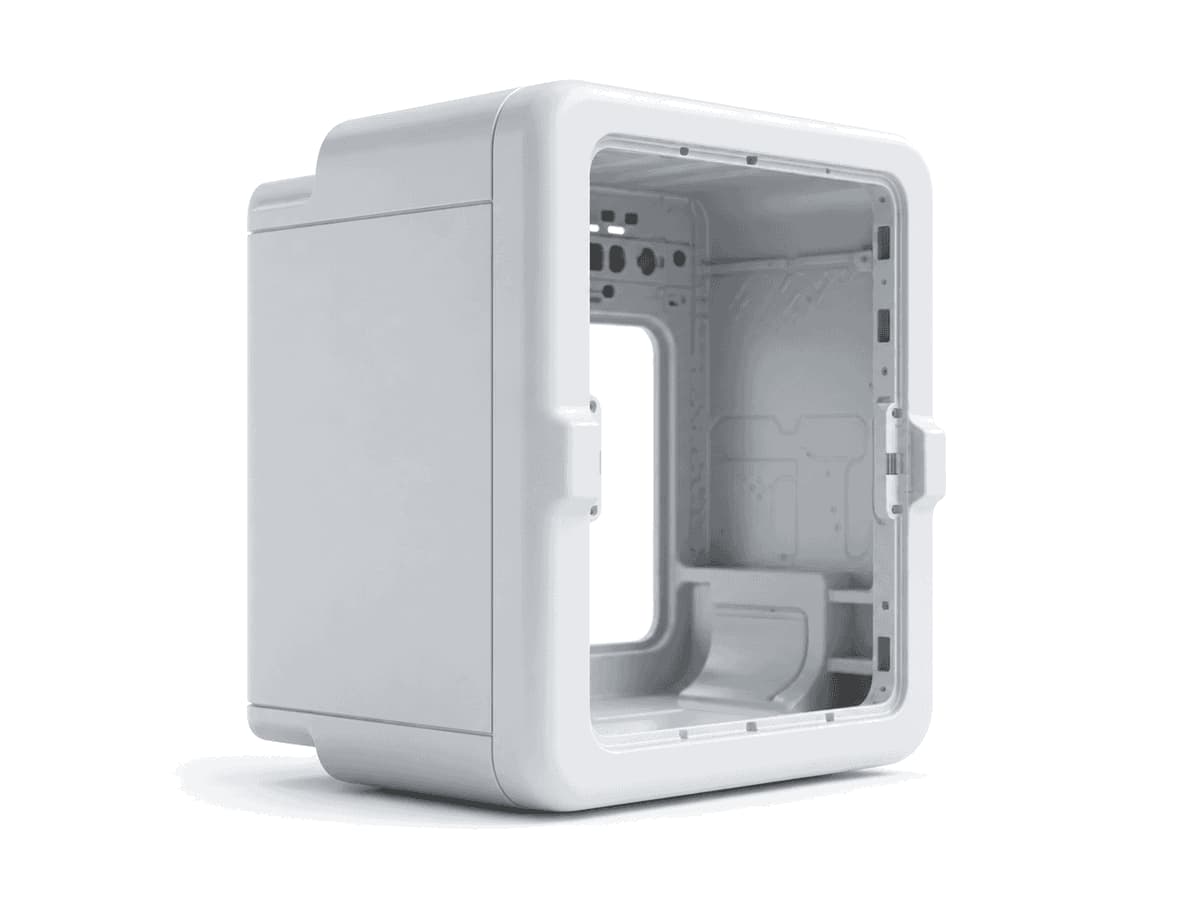
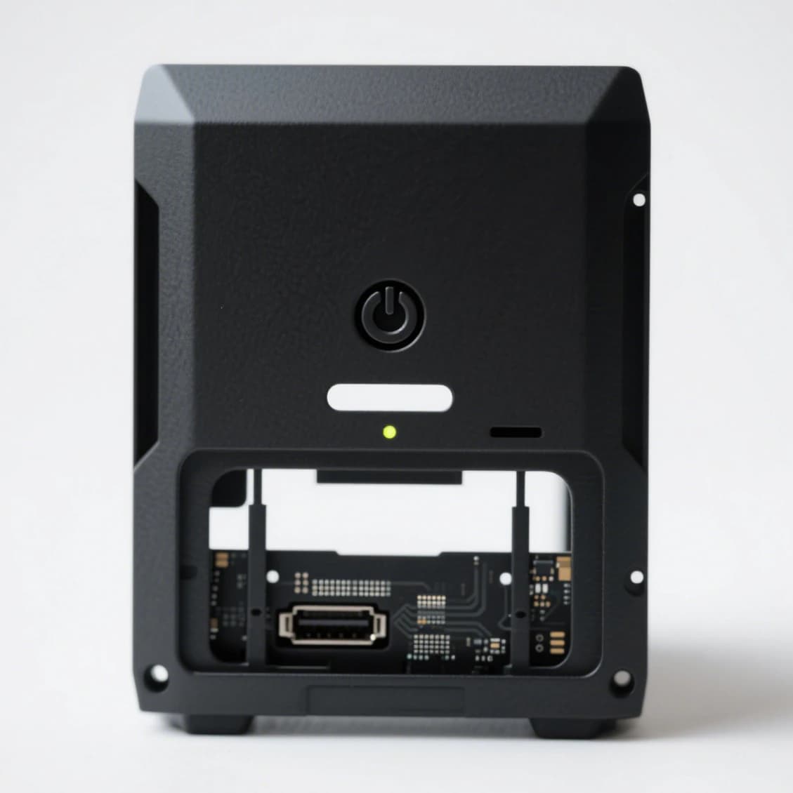
Before committing to production injection molds, consumer-electronics and hardware teams need to know whether a new product looks right, fits together, and communicates the intended quality. A CAD model or digital rendering cannot fully answer questions about color separation, surface gloss, transparent windows, button feel, or the appearance of a finished assembly.
That is where appearance and fit-check prototypes become valuable. With CNC machining, 3D-printed master patterns, silicone mold vacuum casting, and carefully selected decorative processes, teams can evaluate many production-like visual details without investing immediately in hard injection-molding tools. The goal is not to duplicate the production process itself; it is to create a convincing physical reference for design approval and early-stage evaluation.
Why Simulate Production Finishes Before Tooling?
Production techniques such as two-shot injection molding, in-mold labeling (IML), and in-mold decoration (IMD) can deliver integrated color, graphics, and surface effects. However, developing production tools before the product design is approved can make changes expensive and slow.
An early prototype can help a development team review:
- Color, texture, gloss, and branding against an approved appearance reference.
- Housing geometry, component alignment, clearances, and basic assembly fit.
- The location and perceived feel of soft-touch grips, keys, or raised decorative features.
- Whether a design is ready for tooling discussions, customer presentations, or a pilot build.
For a small number of samples, a combination of machining, silicone tooling, and secondary finishes is often more practical than commissioning production molds. Suitability depends on geometry, materials, finish complexity, quantities, and the intended evaluation.
1. Simulating Two-Shot Molding: Two Colors and Hard–Soft Surfaces
Two-shot injection molding combines two materials or color regions within a production molding cycle. Prototypes can reproduce aspects of the visual effect using different approaches, even though the materials and interfacial bonding are not necessarily equivalent to production parts.
Option A: Precision Masking and Multi-Color Painting
For smooth housings and clearly defined color zones, technicians can mask selected regions and apply separate coating layers. Gloss, matte, or other specified finishes can be evaluated on the same physical prototype.
Best suited to: two-tone consumer-electronics housings, cosmetic panels, and presentation models. The main limitations are masking-line quality, coating thickness, edge durability, and repeatability.
Option B: Sequential Vacuum Casting for Hard–Soft Effects
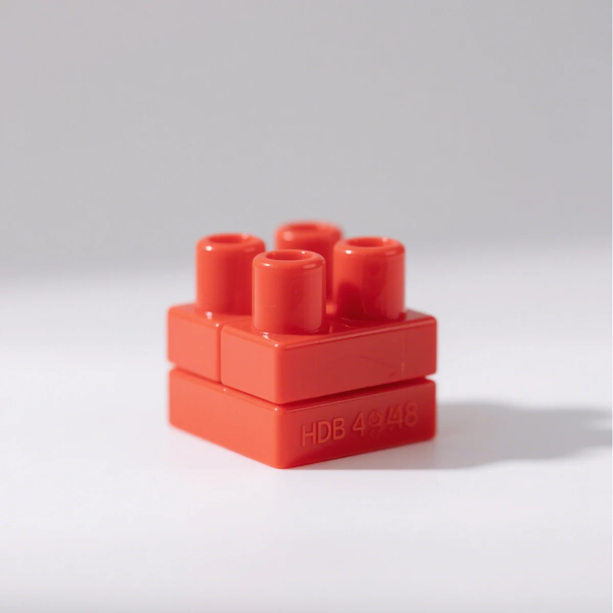
For soft-touch areas, a rigid polyurethane casting can be produced first and then positioned as an insert in another silicone mold. A compatible elastomeric polyurethane is cast around selected areas to create a hard–soft appearance, such as a grip or button surround.
This approach can help assess visual transitions and ergonomics. However, cast polyurethane systems should not be presented as chemically or mechanically identical to production ABS, PC, TPU, or TPE. Material compatibility, adhesion, shrinkage, and long-term durability require separate evaluation.
Option C: Colored Resin Filling and Localized Doming
Logos, indicator recesses, and small decorative details can be filled with colored or transparent resin. A controlled domed finish can also add a localized raised or glossy effect. These methods are useful for appearance studies but do not automatically reproduce the feel or wear performance of a production-molded key.
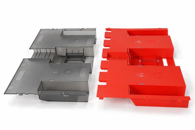
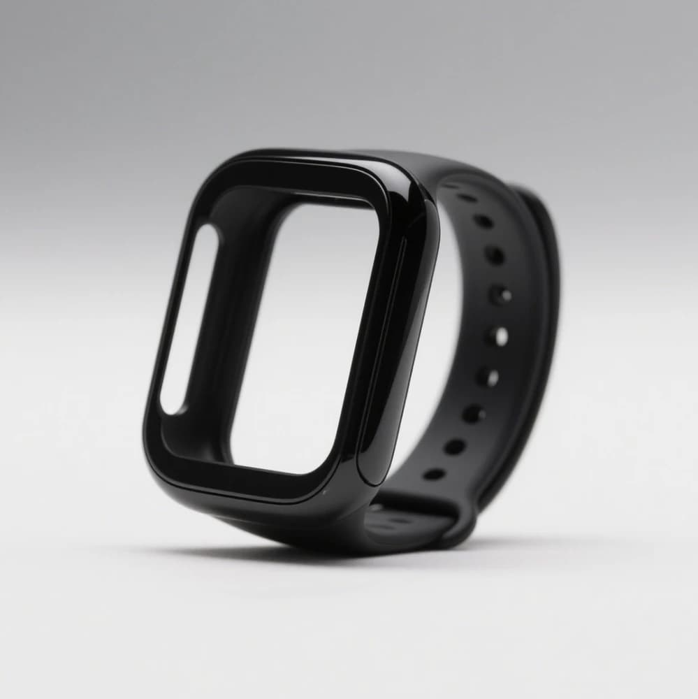
2. Creating an IML/IMD-Like Appearance Without Production Injection Molds
In production, IML and related IMD processes integrate a printed label or decorative film with a molded plastic part. Depending on the process, a flat or preformed film is placed in the injection mold and becomes part of the finished assembly. Prototype techniques can imitate the visible film and graphic effects, but they do not reproduce the same in-mold bonding mechanism.
Option A: Printed Decals or UV-Printed Graphics
Printed adhesive graphics or suitable direct-to-part UV printing can reproduce flat artwork, logos, and color blocks on a prototype surface. This is often a straightforward route for early visual reviews and presentation samples.
Limitations: edges may remain visible; abrasion resistance and environmental durability depend on the ink, coating, substrate, and adhesive. A surface-applied graphic should not be described as genuine IML.
Option B: Formed PET/PC Decorative Film and Lamination
For curved control panels or decorative housings, a printed PET or PC film can be formed to match the surface geometry, trimmed, aligned, and bonded to a CNC-machined or cast substrate. Reverse printing beneath a clear film may provide visual depth and help protect the artwork in a display prototype.
This option is particularly useful when teams want to evaluate a film-covered appearance before investing in injection tooling. Film thickness, stretching, graphic distortion, edge fit, trapped air, and adhesive compatibility must be checked. A formed film does not by itself create realistic button actuation or the durability of an injection-integrated film.
Option C: Clear Resin Doming for Selected Details
A transparent resin dome placed over artwork can imitate the glossy, raised appearance of individual icons, badges, or buttons. It works best for localized details, not for reproducing a large continuous in-mold decorative film.
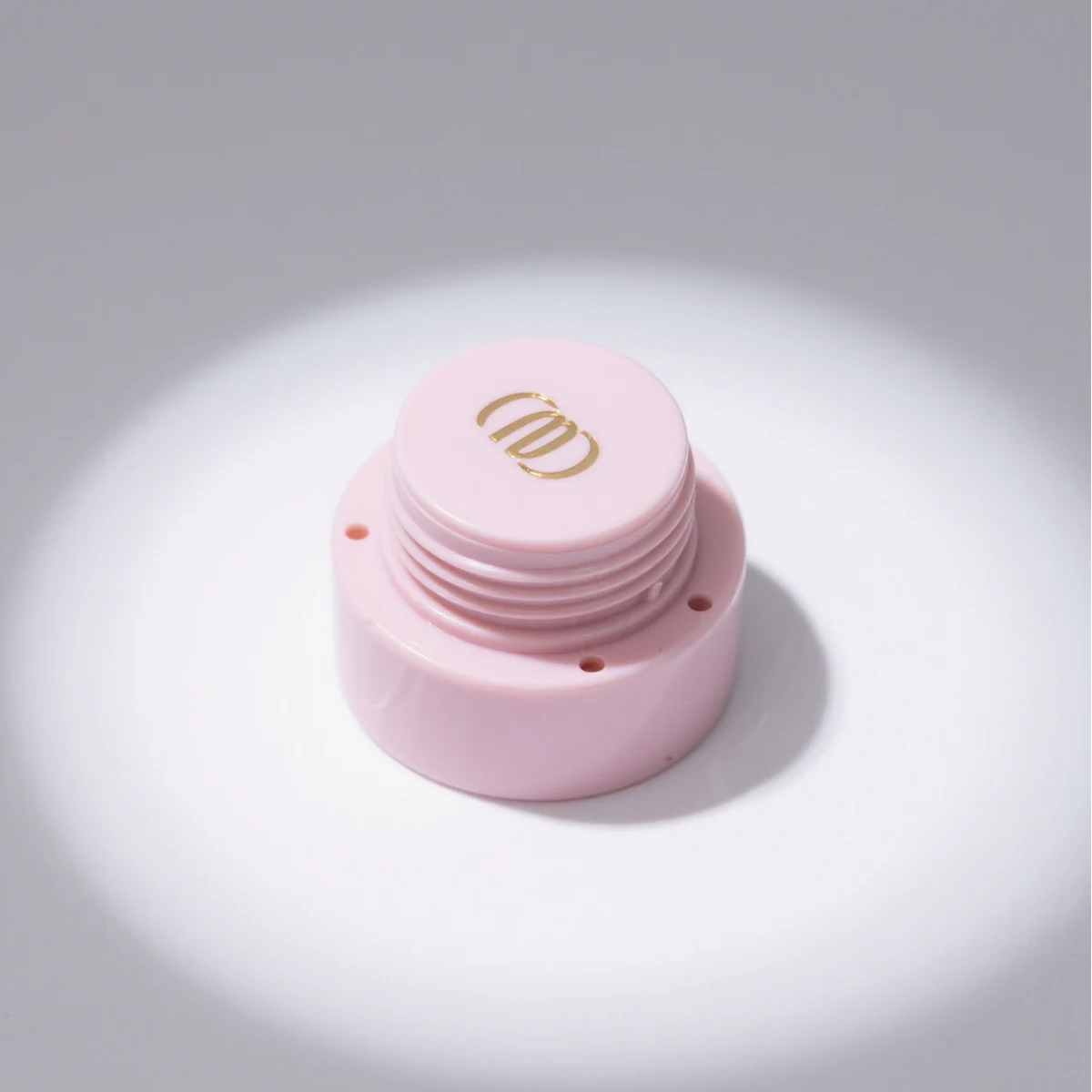
3. Simulating IMR-Style Graphics and Textures
IMR is commonly used to describe a film-based in-mold transfer decoration process. Unlike a retained decorative film, the carrier can separate after transferring the decorative layer during production. For prototypes, similar visual themes can be achieved with secondary surface-decoration techniques.
Direct UV Printing and Transfer Graphics
Depending on part geometry and surface preparation, direct UV printing or separately applied transfer graphics can reproduce woodgrain, stone-like patterns, logos, and other designs. Surface curvature, ink adhesion, alignment, and wear exposure govern the choice of method.
Hydrographic Printing (Water Transfer Printing)
Hydrographic printing can apply decorative patterns across suitably prepared three-dimensional surfaces. It is often considered for carbon-fiber-look, camouflage, woodgrain, or other complex graphic effects on curved housings.
It is important to distinguish visual imitation from material performance: a carbon-fiber-pattern transfer is not a structural carbon-fiber composite. Protective topcoats, edge coverage, and finish durability should be specified separately.
4. Which Prototype Process Should You Choose?
| Design goal | Practical prototype approach | Key limitation to evaluate |
|---|---|---|
| Two-color housing | Precision masking + multi-color painting | Mask lines, coating durability |
| Hard–soft grip or bezel | Sequential rigid/soft polyurethane casting | Bond strength, tactile and material mismatch |
| Flat logo or graphic | Printed decal or direct UV printing | Edges, scratching, adhesion |
| Curved IML/IMD-like panel | Formed printed PET/PC film + bonding | Film distortion, fit, delamination |
| Raised icon or decorative key | Localized clear resin doming | Limited tactile and mechanical fidelity |
| Woodgrain or carbon-fiber-look texture | Hydrographic or compatible graphic transfer | Coating wear, visual consistency |
The most effective solution is often a combination of processes. For example, a CNC-machined PMMA window or a cast housing may be paired with a painted body, formed graphics, and localized decorative elements—provided each process is compatible with the base material and evaluation requirements.
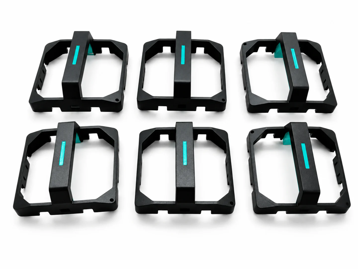
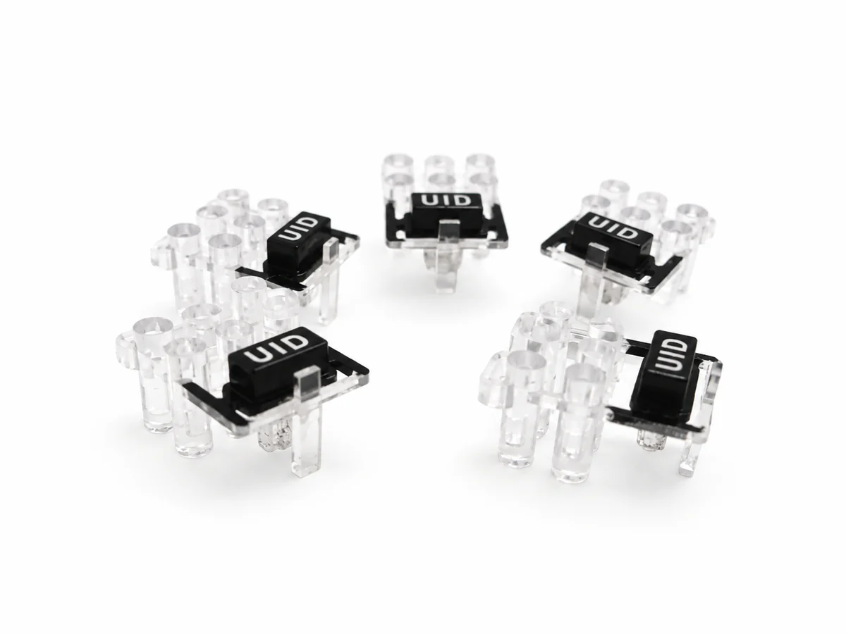
Explore our CNC prototyping services for drawing-led appearance and assembly-fit review.
5. A Practical Workflow From CAD to Appearance Approval
- Define the prototype objective. Separate appearance and assembly questions from tests that require production materials or certified performance.
- Select the master-part process. CNC machining is well suited to many precise metal, acrylic, and engineering-plastic parts; 3D printing may be useful for complex masters and selected form studies.
- Choose the replication method. For a limited number of similar plastic samples, a silicone mold and suitable casting resin may reduce repeated master-part machining. Mold life and dimensional consistency should be reviewed.
- Prepare a color–material–finish (CMF) reference. Supply color targets, surface texture, gloss level, artwork, graphic alignment, and appearance samples when available.
- Apply and inspect decorative finishes. Review color in agreed lighting, surface defects, film alignment, masking edges, coating adhesion, and dimensional fit.
- Approve the prototype, then validate production feasibility. Injection-mold tooling, resin choice, in-mold film design, and production durability still require dedicated engineering review.
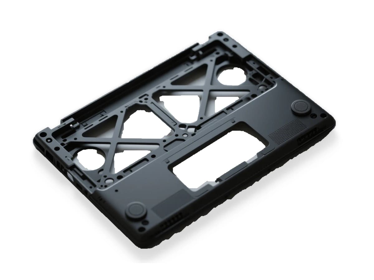
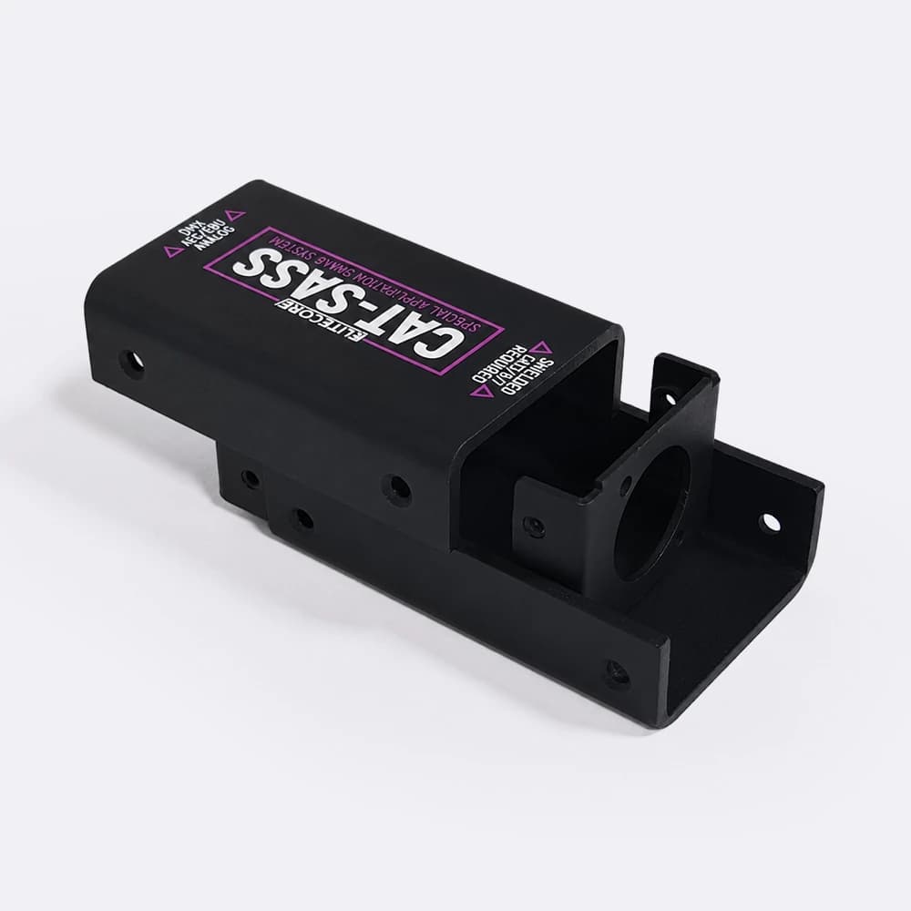
For products that combine decorative plastic housings with metal support structures, prototype planning may also involve sheet-metal brackets, mounting frames, or bent enclosures. These supporting components can be evaluated through sheet metal bending before final assembly and tooling decisions.
6. What a Prototype Can—and Cannot—Prove
A well-made prototype can be a strong reference for industrial design, early assembly review, packaging photography, trade-show displays, and stakeholder approval. It can also expose visual or mechanical-fit issues before a company commits to hard tooling.
However, a painted part, adhesive film, or cast polyurethane sample should not be assumed to match production injection-molded parts in impact strength, chemical resistance, long-term wear, waterproofing, UV aging, or in-mold film adhesion. Silicone molds also have a limited service life, so appearance consistency and quantity need to be agreed for each project.
If a product must pass functional or regulatory testing, the prototype materials and processes must be selected specifically for those tests. A convincing appearance model is not a substitute for validated production performance.
7. What to Send for a Prototype Quotation
To assess the most suitable process, prepare the information that affects feasibility, finish quality, lead time, and cost:
- 3D CAD files and any 2D drawings identifying critical dimensions or fit requirements.
- Expected quantities, including the number of design revisions or cosmetic variants.
- Preferred material or target material feel, plus any hard–soft interface requirements.
- Artwork files, color references, gloss/texture requirements, and photographs of the intended finish.
- The specific purpose of the sample: visual review, assembly fit, presentation, or a defined test.
- Required delivery date and any inspection or acceptance criteria.
At HERUIYUN, you can share your CAD data and appearance references for a project-specific manufacturing review. The right combination of CNC machining, silicone mold casting, and decorative finishing depends on the design and the level of fidelity you need.
From appearance approval to a small pilot batch
Approving a cosmetic sample does not automatically approve repeated production. A film, sprayed finish or cast polyurethane part may reproduce the intended appearance without reproducing the mechanical properties of the molded production material. Before requesting 10–50 samples, agree what must remain consistent: colors, gloss, texture, fit surfaces and the reference artwork revision.
Treat appearance acceptance and functional-fit acceptance as separate checks. If a prototype must also locate bearings, support a snap fit or hold a precision mating feature, the DFM review should distinguish the necessary geometric controls from the cosmetic finish. A second process or inspection step may be needed.
For the engineering handoff, see Custom CNC Parts: From Functional Prototypes to Low-Volume Production. It explains how to plan functional datums, quantities, first-article checks and batch-level RFQs after the design direction is approved.
Frequently Asked Questions
Can rapid prototypes exactly reproduce production IML or IMD?
They can closely simulate selected colors, graphics, surface depth, and tactile features, but surface-applied films or finishes do not duplicate the bonding, wear characteristics, or processing history of genuine in-mold decoration.
Can vacuum casting create a hard–soft prototype?
Yes, two-material silicone mold casting can produce hard–soft effects with compatible casting resins. Adhesion and mechanical performance are project-specific and should be tested rather than assumed.
Does vacuum casting eliminate the need for molds?
No. It uses a silicone mold rather than a production injection mold. The benefit is the ability to replicate limited quantities before investing in harder, more expensive production tooling.
Is this suitable for 1–100 prototype parts?
Potentially, but no single process or silicone mold is suitable for every quantity. Part size, geometry, finish complexity, resin, and mold life determine whether one-off machining, vacuum casting, or another approach makes more economic sense.