
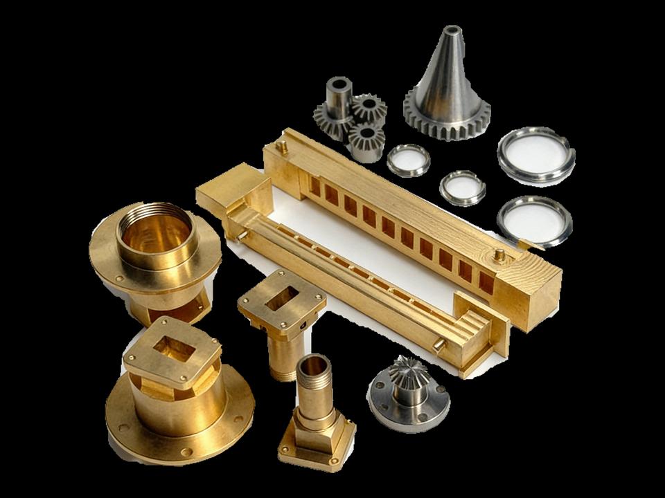
CNC Machining
- Lead time: 3–7 days
- Tolerance: ±0.01 mm (down to ±0.005 mm)
- MOQ: 1 part
- ISO 9001 / ISO 13485
Custom metal and plastic prototypes for appearance review, assembly verification and functional development—from drawings to production planning.
Manufacturing route, material, tolerance and delivery requirements are confirmed during engineering review.
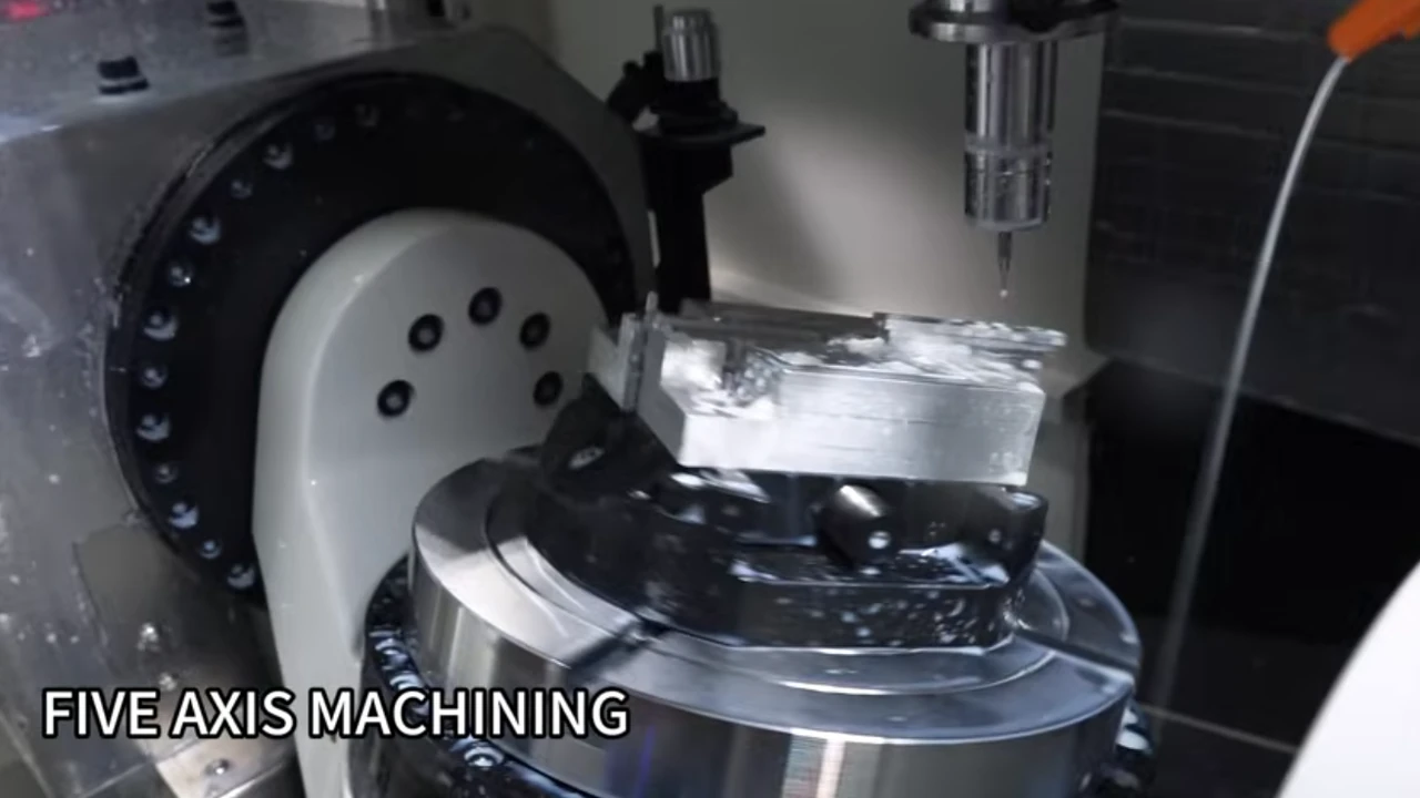
Prototype Manufacturing Process
OUR PARTNERS





CNC housings, bezels, covers, front panels & snap-fit components.
Matte, gloss, polishing, painting & Pantone/RAL color matching.
ABS, PC, POM, PEEK & Nylon.
2–7 days for selected prototypes.
Prototype to Low-Volume1 Part Welcome · Assembly Fit · Design Iterations · Small Batches
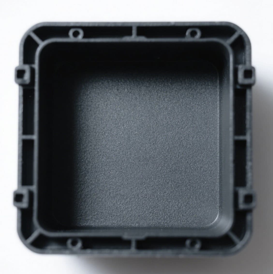
Internal pockets, mounting features and enclosure assembly fit.
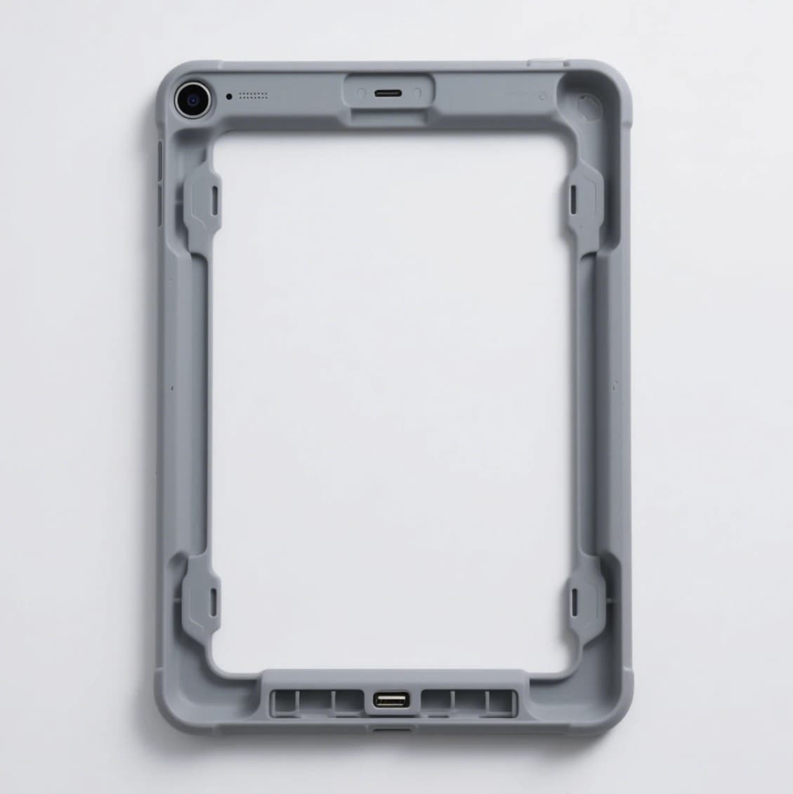
Snap-fit features, mating edges and component interfaces.
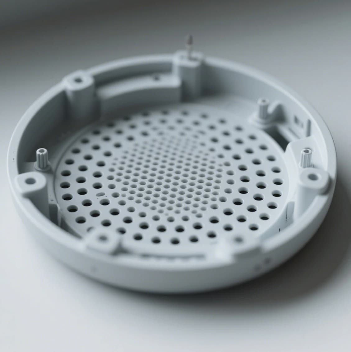
Precision openings, ventilation geometry and enclosure alignment.
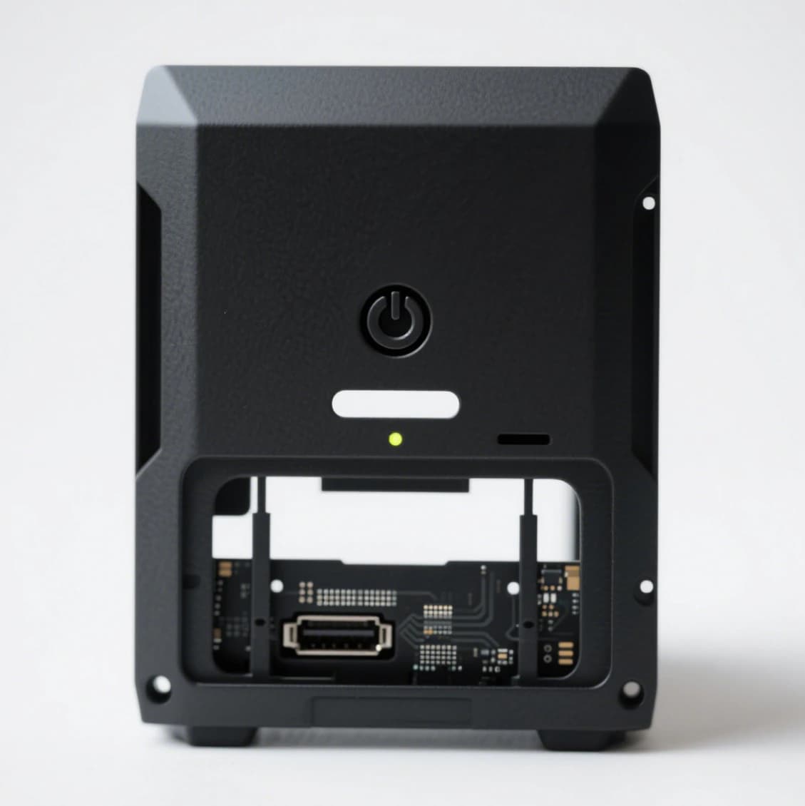
Connector openings, control placement and external appearance.
Diagnostic housings, imaging covers, clinical-cart panels & mounting parts.
3/4/5-axis CNC, precision interfaces, polishing & painting.
ISO 13485 quality management · PEEK, PC, POM, aluminum & stainless steel.
NDA support, engineering review & low-volume manufacturing.
Inspection & DocumentationDrawing-Based Inspection · CMM/FAI Options · Material Documentation
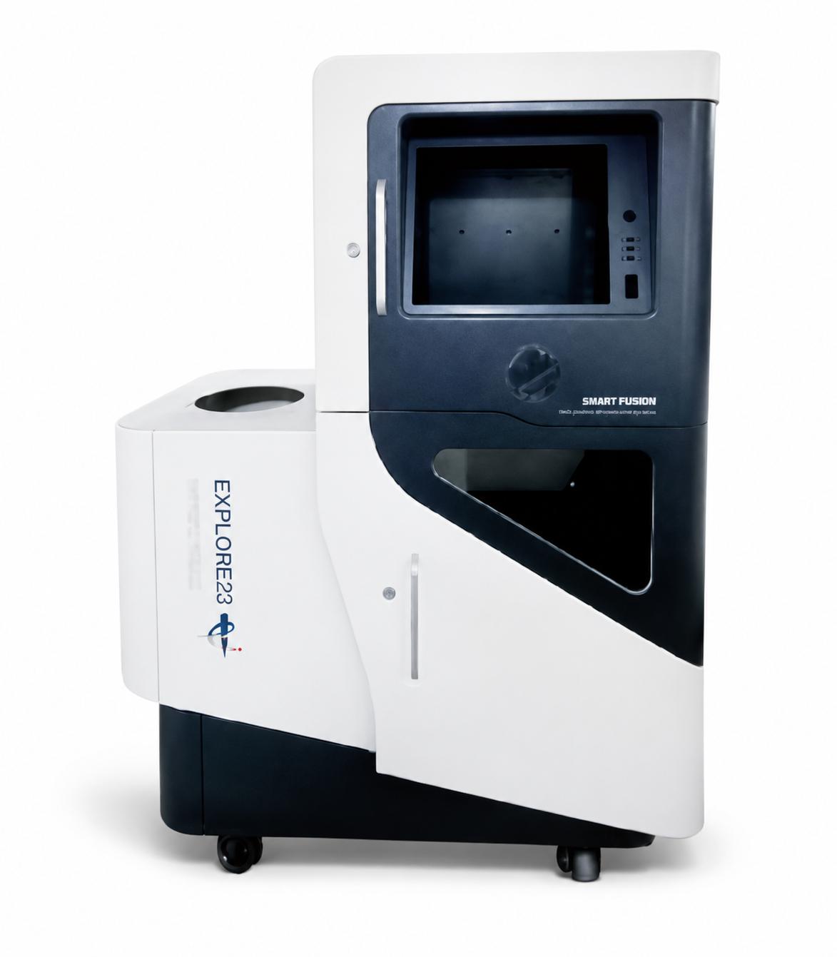
Housing panels, internal mounting features and interface clearances.
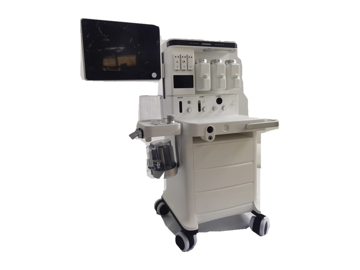
Equipment enclosures, access panels and component mounting interfaces.
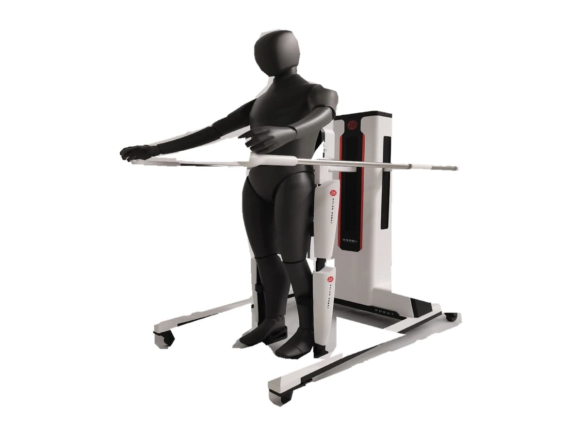
Structural supports, mounting geometry and mechanical assembly review.
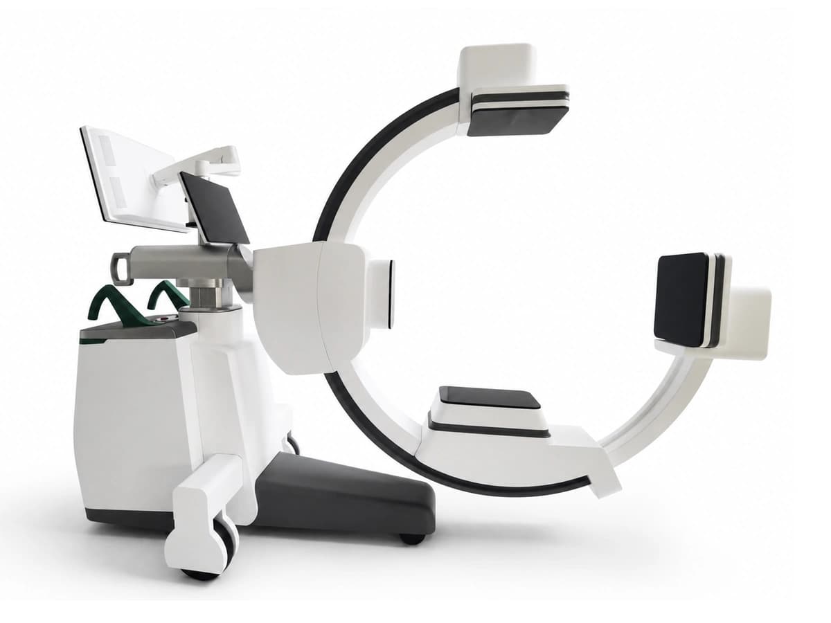
Imaging-system covers, equipment frames and alignment interfaces.
Mounting brackets, mechanical housings, turned parts & translucent covers.
Critical features down to ±0.01 mm · PMMA/PC tinting & fit checks.
Aluminum 6061/7075, stainless steel · Precision milling & turning.
ISO 9001 quality management · CMM/FAI & material documentation options.
Finishes & Small BatchesAnodizing · Polishing · Painting · Coating Options · Low-Volume Production
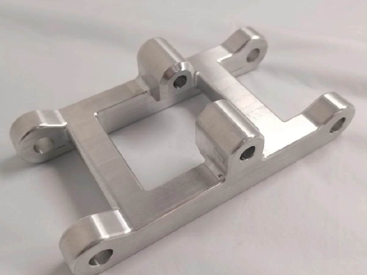
Mounting-hole precision, bracket geometry and assembly fit.
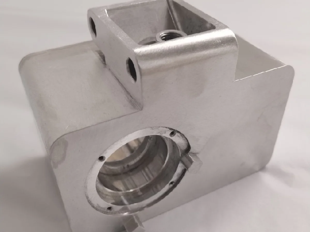
Precision bores, machined pockets and mating interfaces.
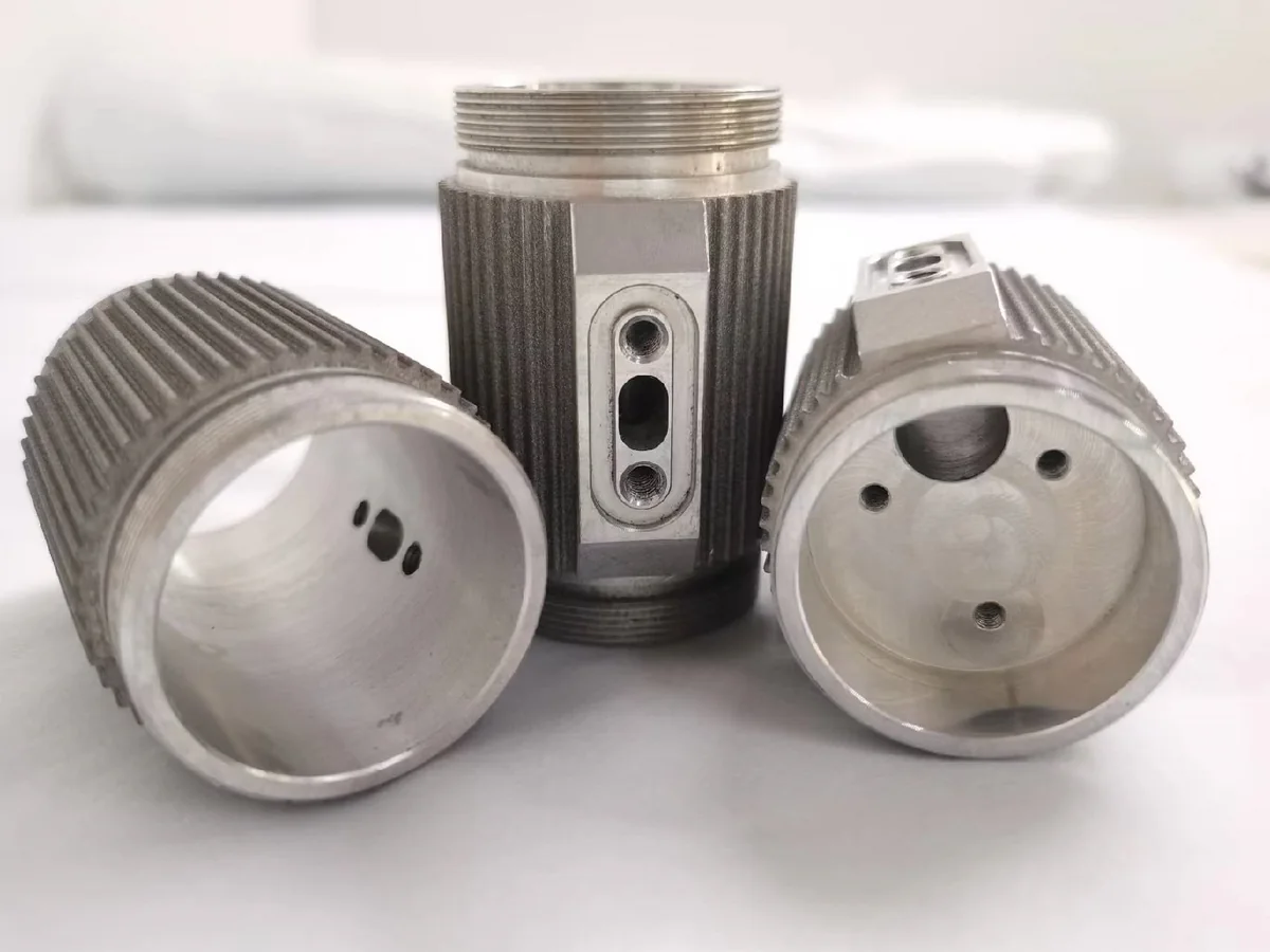
Turned diameters, concentricity, threaded features and mechanical fit.
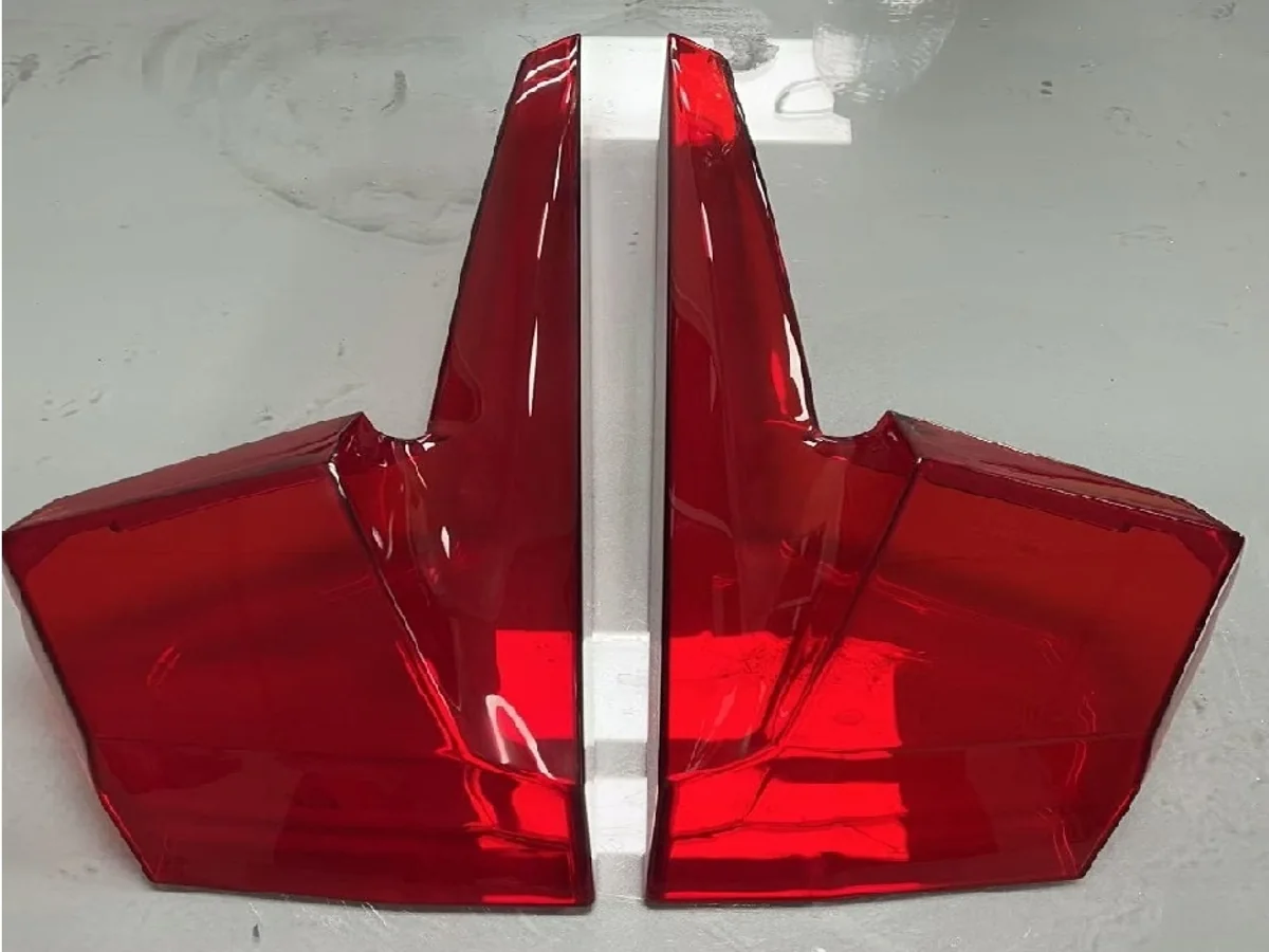
Custom tint, translucency, surface appearance and cover fit.
Joint housings, actuator mounts, AGV shells & lightweight brackets.
Bearing bores, shaft interfaces, threaded inserts & mounting alignment.
Aluminum 6061/7075, engineering plastics · CNC, 3D printing & vacuum casting.
Engineering review, fit checks, design revisions & small-batch production.
Mechanical PrecisionJoint Alignment · Concentricity · Bearing Fits · Sub-Assembly Support
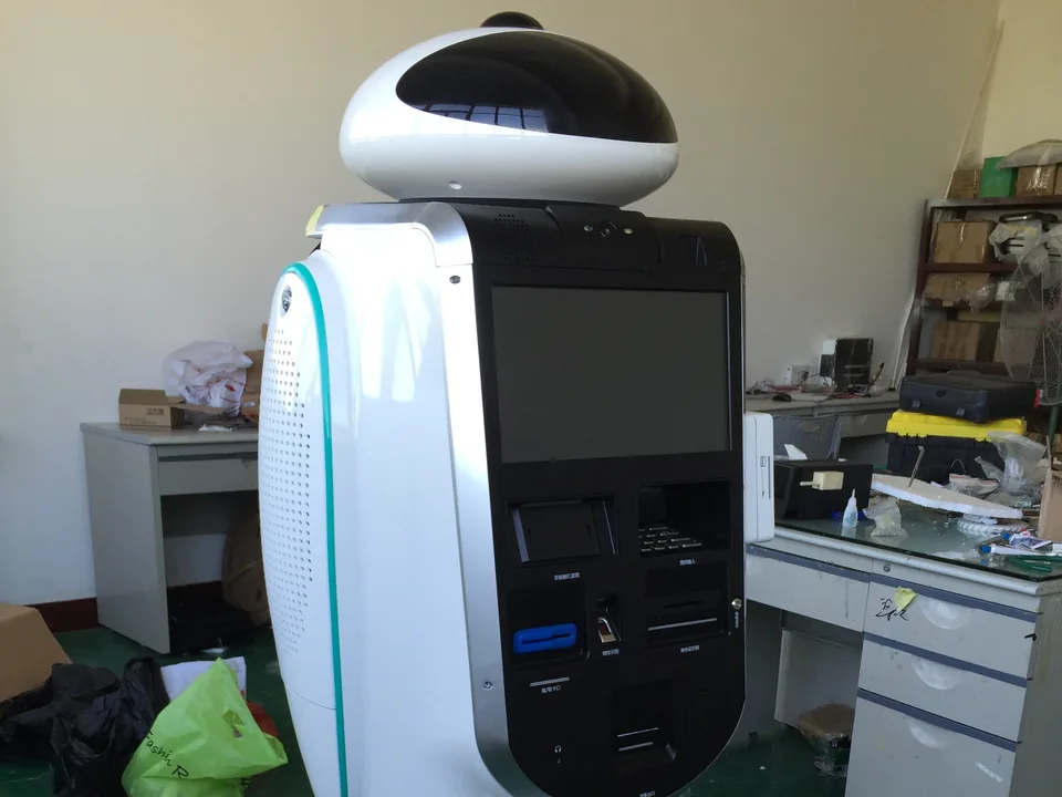
Enclosure fit, display openings and internal mounting interfaces.

Joint clearances, actuator mounting and structural alignment.
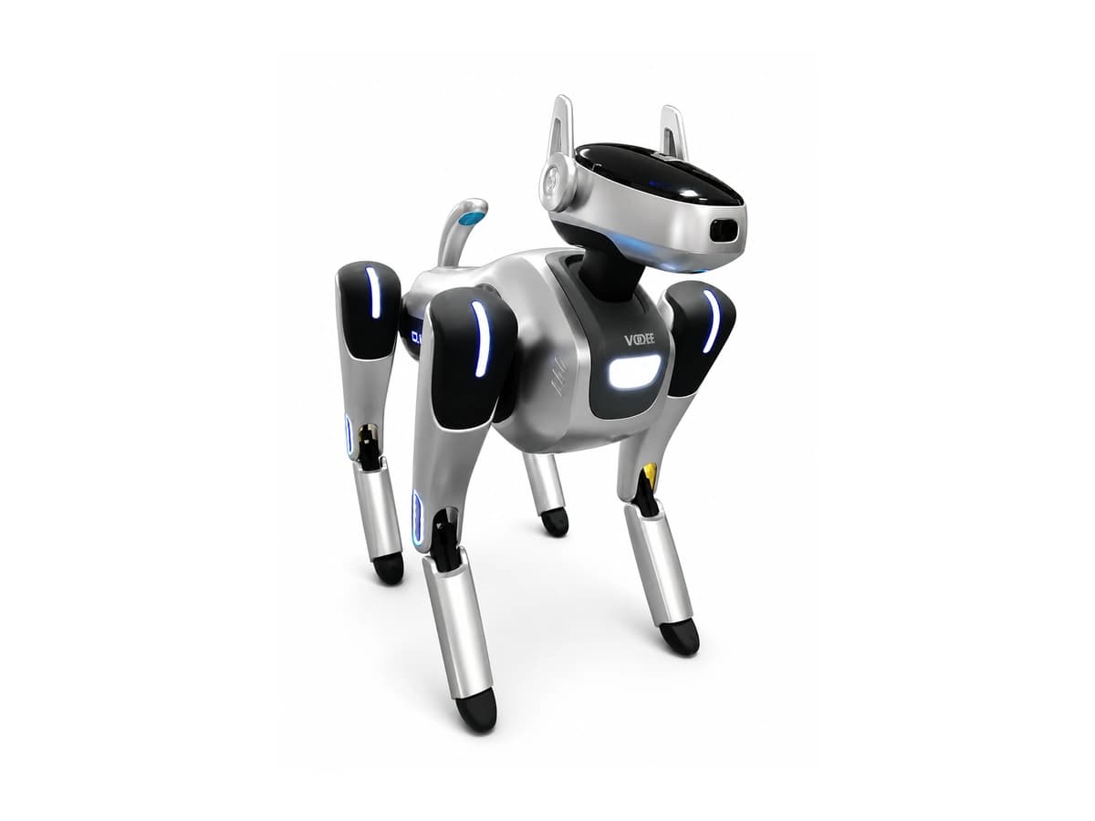
Lightweight body structures, leg interfaces and assembly fit.

Protective housings, sensor openings and maintenance access.
Cold plates, 19" rackmount panels, chassis frames & airflow shrouds.
Copper & aluminum contact surfaces · Ra < 0.4 μm · Flatness control.
Copper, Al 6063, PC/ABS · UL 94 V-0 flame-retardant material options.
3-day options for eligible parts · Rapid DFM & small batches.
Cooling & Assembly SupportPrecision Flow Channels · Pressure/Leak Testing Options · PEM Fasteners · CAD Review
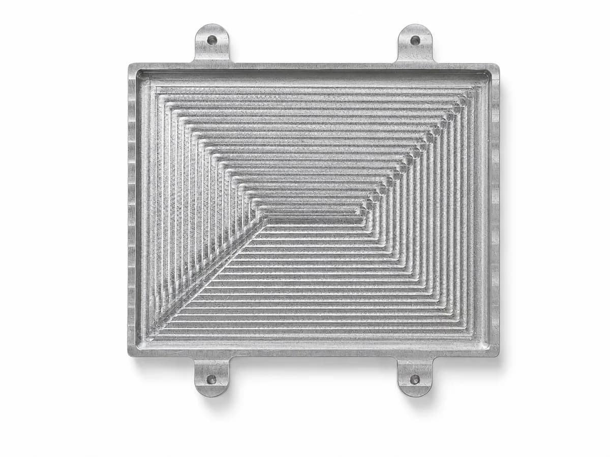
CNC-machined cooling channels, flatness control and thermal interface features.
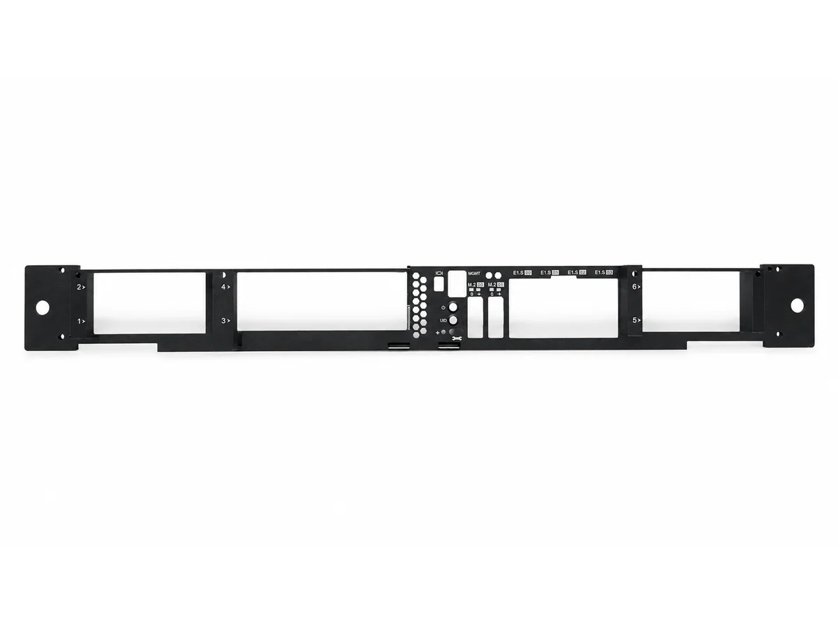
Precision port cutouts, connector alignment and mounting interfaces.
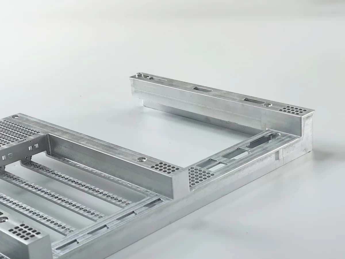
Rackmount geometry, structural alignment and assembly fit.
Custom airflow paths, component clearances and housing integration.
Select the alloy and condition around mechanical requirements, weight, corrosion behavior and finishing.
Review temperature, moisture, stiffness and dimensional behavior for the specified grade and stock form.
Exact grade, condition, stock form and process availability are confirmed during quotation.
Existing physical product examples support appearance review. Photography and screen colors are previews; the final finish is agreed against the specified process and approved sample.
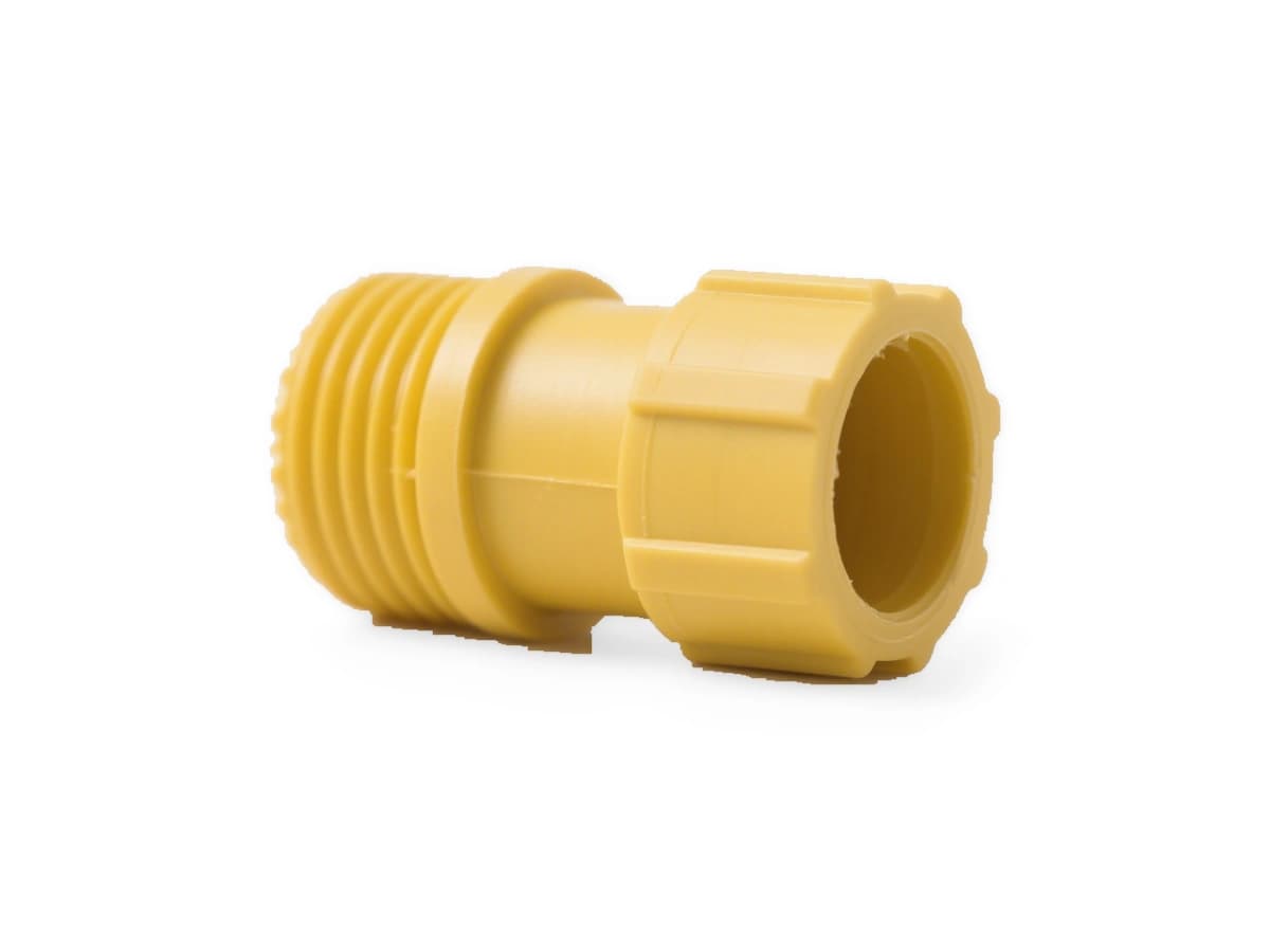
Colored surface
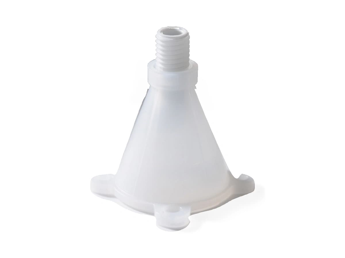
Translucent surface
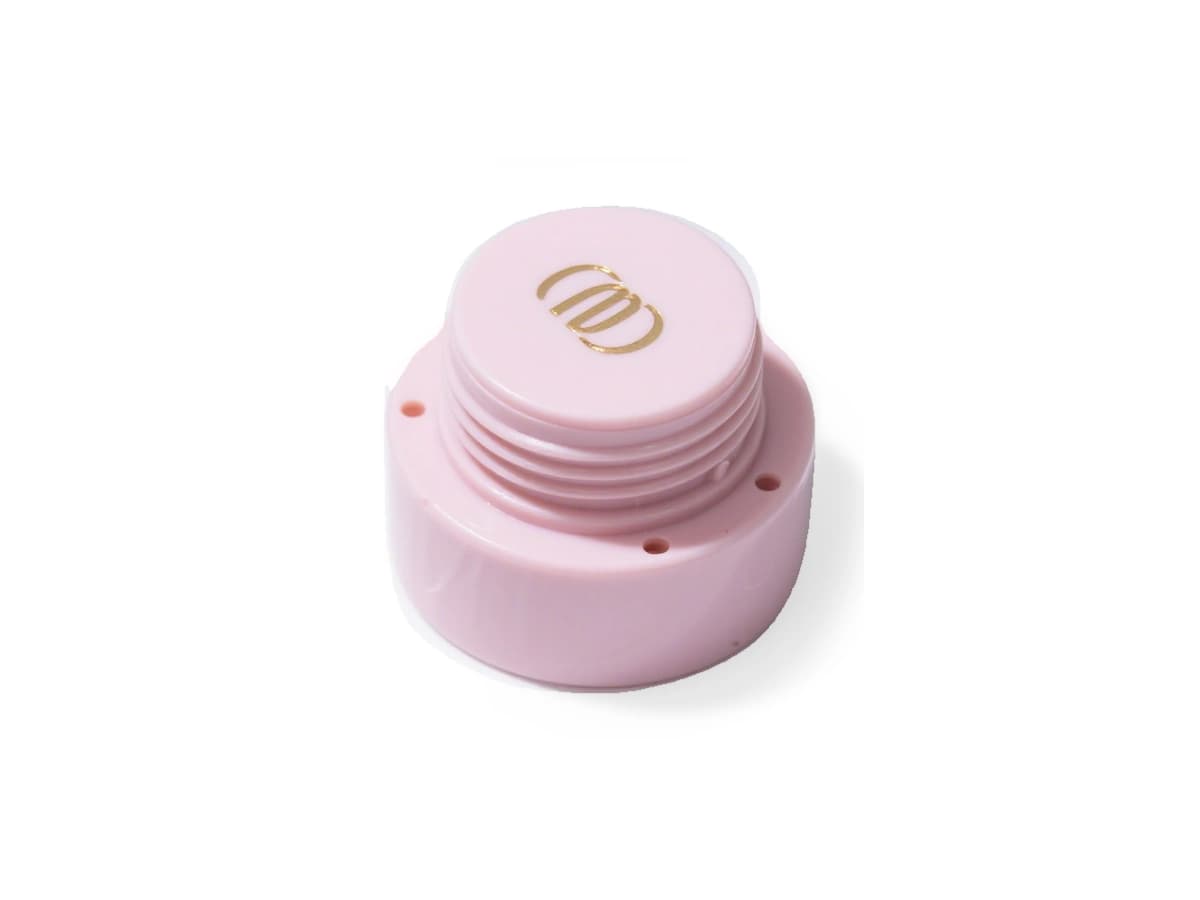
Graphics & surface detail
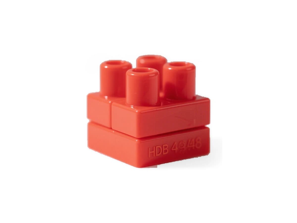
Textured surface
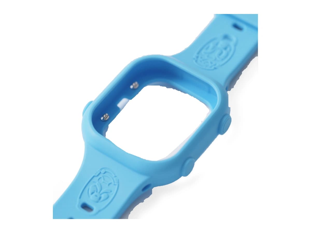
Flexible sample
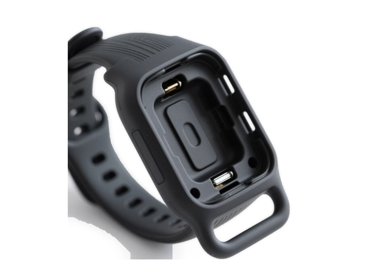
Flexible housing
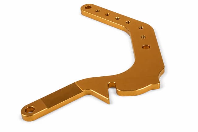
Color and conversion-finish references for machined metal components.
Painted prototype surfaces for color and appearance review.
Coated fabricated parts with protective and cosmetic surfaces.
Matte blast-finish references; the blast medium is confirmed per project.
Reflective metal and clear acrylic surface references.
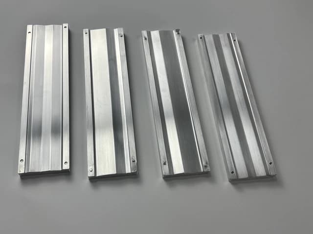
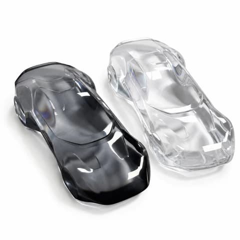
Directional brushing and flocked surfaces show distinct texture options.
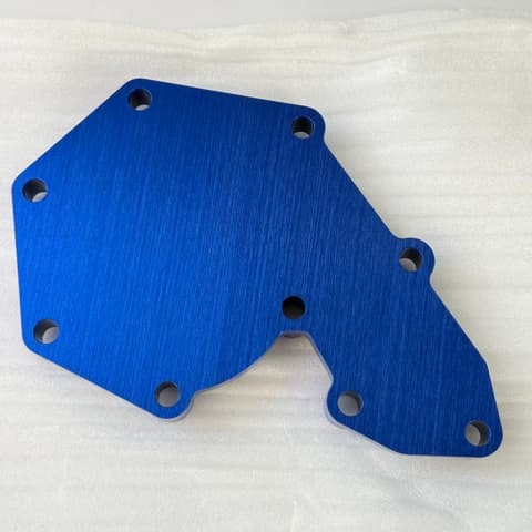
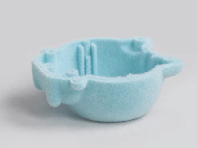
Color and finish specifications are confirmed against the agreed manufacturing process, approved sample, and project-specific acceptance criteria. Digital colors are for reference only.
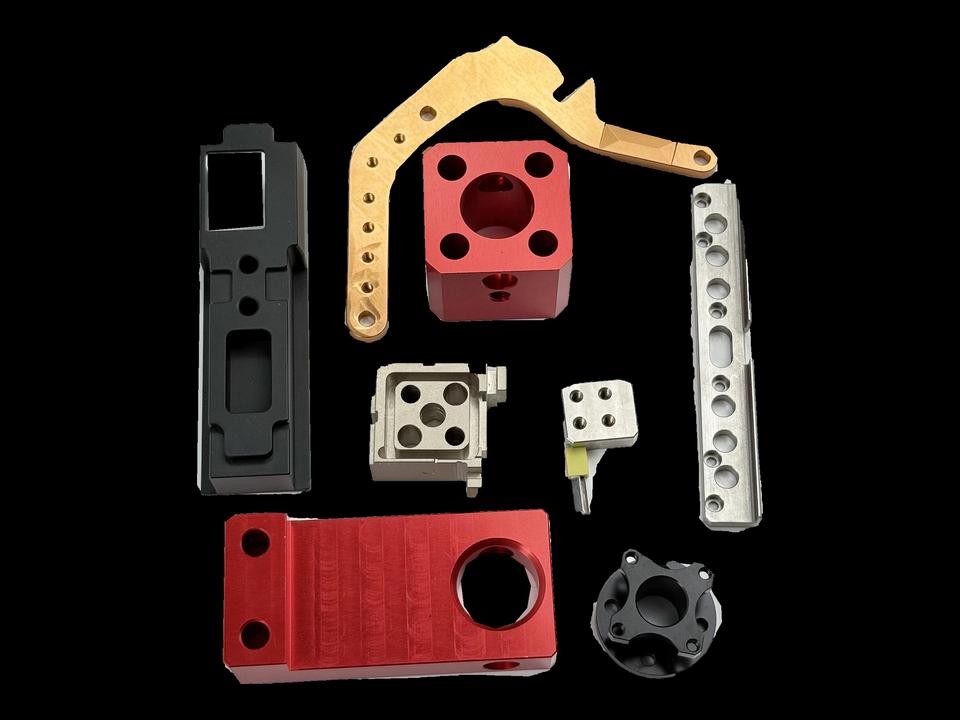
Comprehensive CNC Machining, Secondary Operations & Assembly Integration
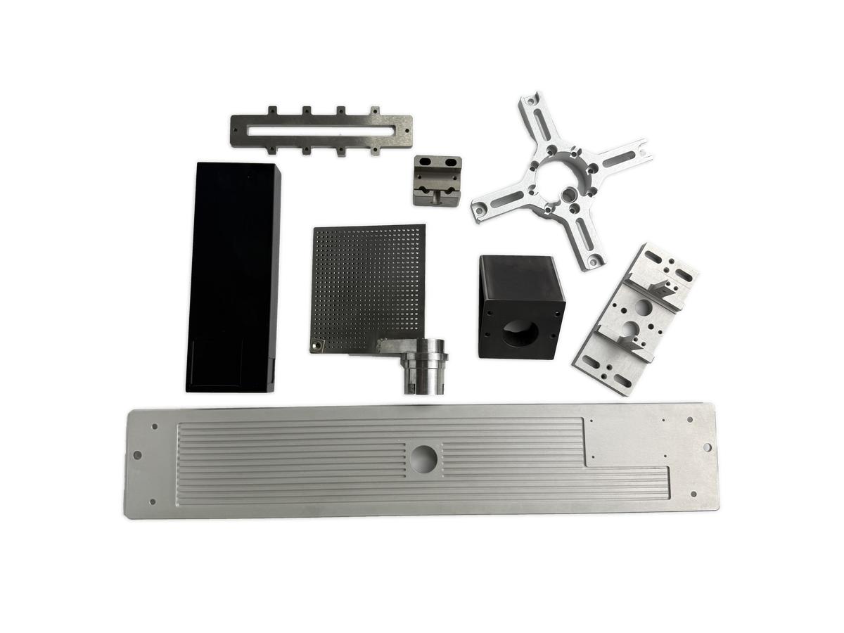
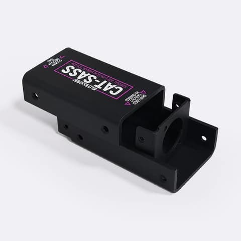
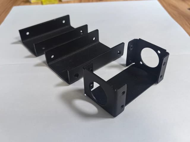
Grooved plates, recessed bodies and slotted mounting features.
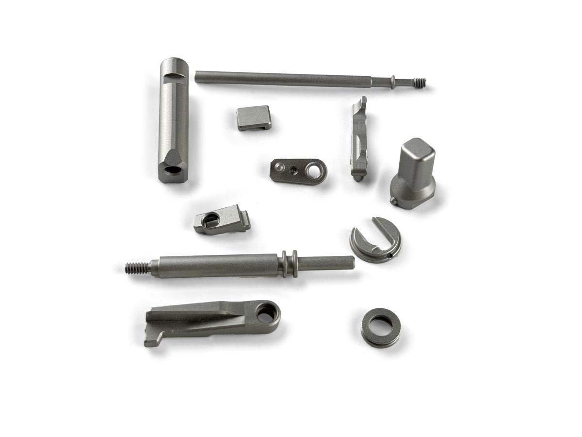
Stepped shafts, threaded ends, cross-holes and flat interface features.
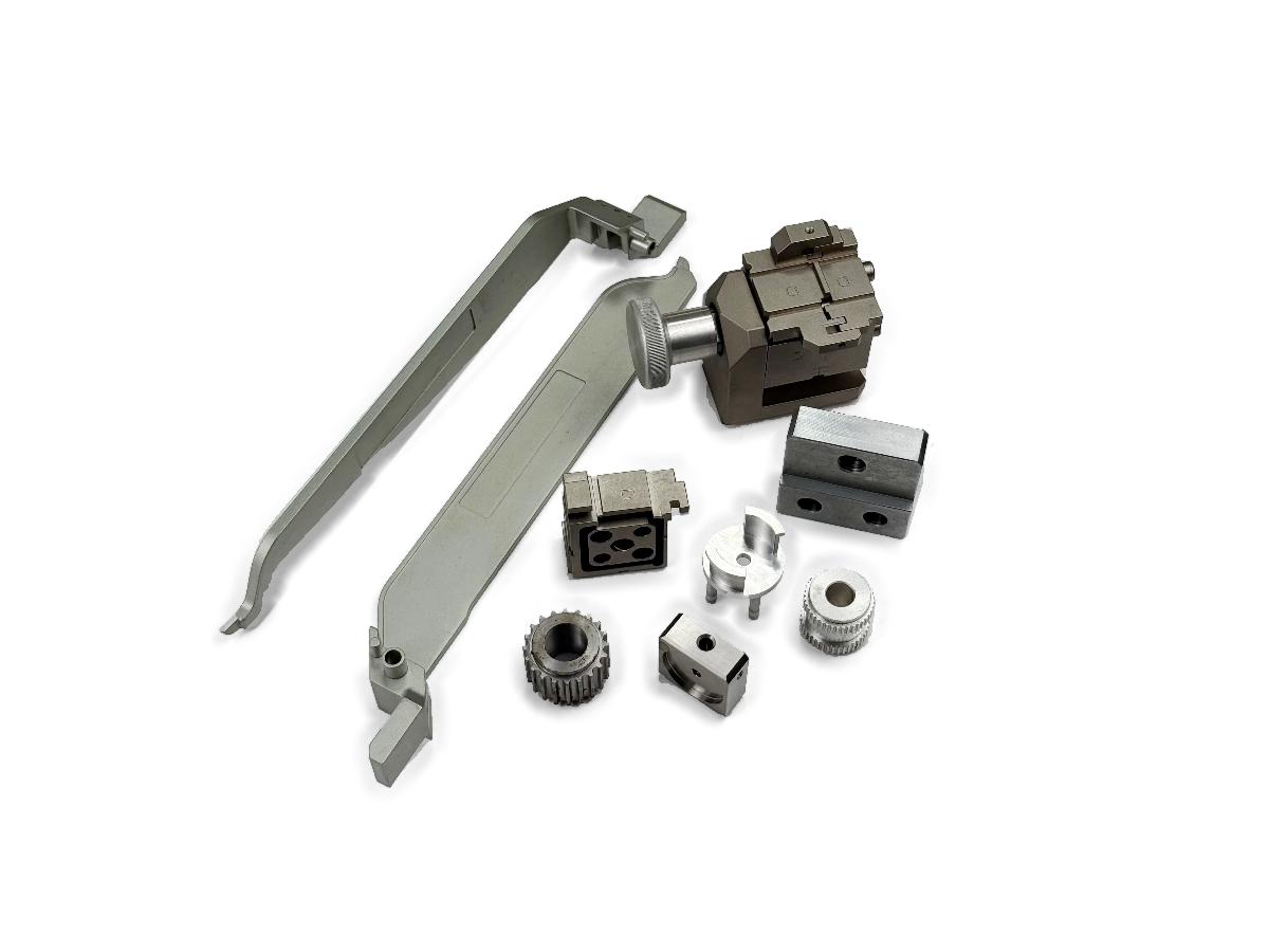
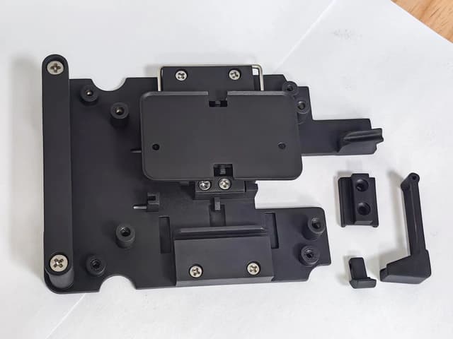
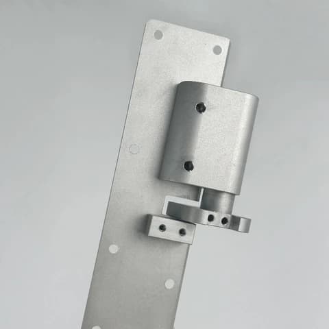
Long mounting arms, clamping blocks and compact parts with bores and slots.
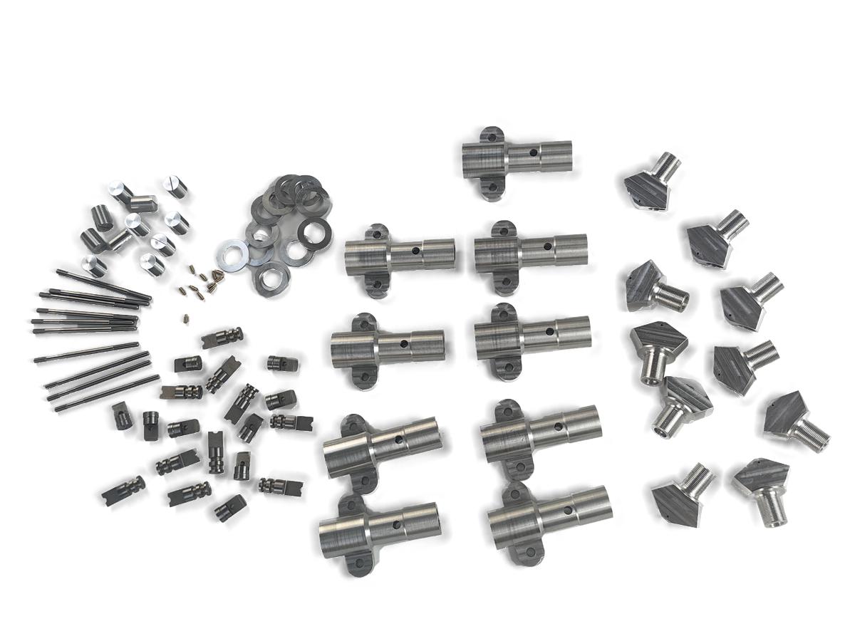
Turned profiles with milled flats, mounting holes and EDM features.
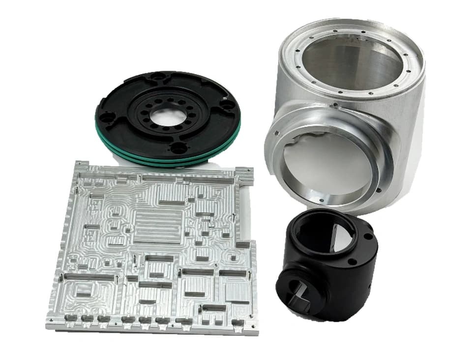
Deep cavities, recessed channels and critical bore features.
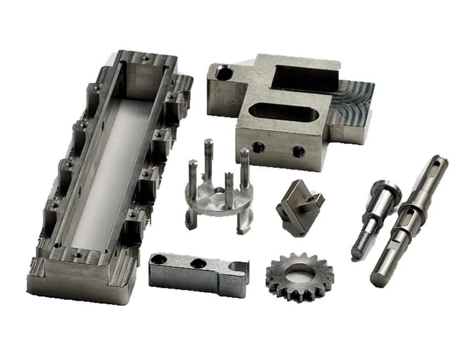
Flat mating surfaces, machined pockets and interface alignment.
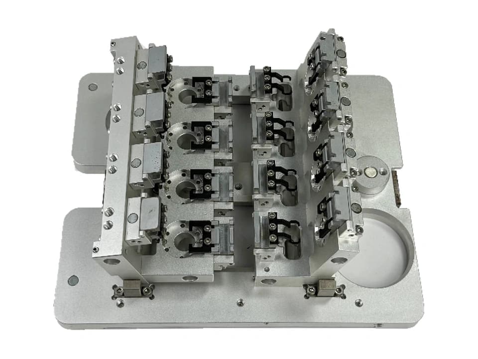
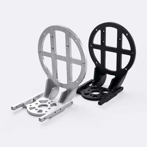
Datum-controlled mounting features, locating structures and precision hole patterns.
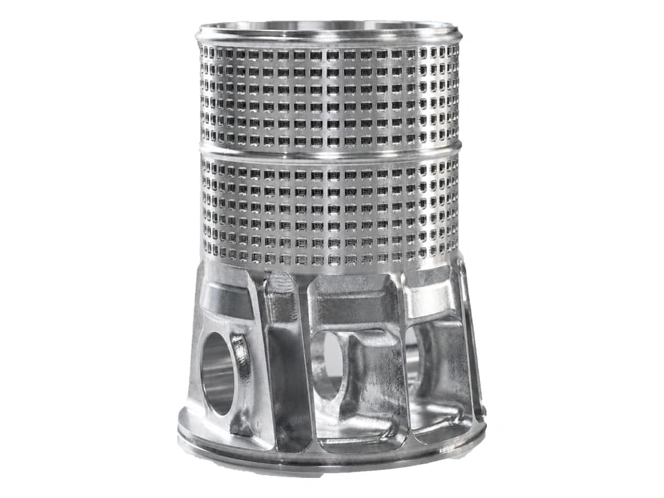
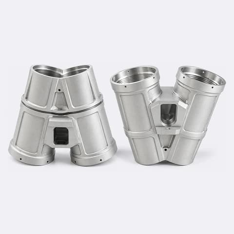
Complex cylindrical geometry, repeated perforations and multi-axis features.
Cost-Effective Bridge Production for 10 to 50+ Production-Grade Parts
| Our Capabilities | Description |
|---|---|
| Maximum build size | 1.8 × 1.5 × 1.2 m |
| Typical mold life | Typically 10–25 parts, depending on geometry and material |
| Tolerance | Refer to the tolerance guide below; critical dimensions are confirmed after drawing review |
| Materials | Rigid, flexible, transparent and colored polyurethane resins |
| Typical lead time | Confirmed after drawing, quantity and finish review |
| Dimensions (mm) | 0–25 | 25–50 | 50–75 | 75–100 | 100–125 | 125–150 |
|---|---|---|---|---|---|---|
| Tolerance (mm) | ±0.3 | ±0.35 | ±0.4 | ±0.45 | ±0.5 | ±0.55 |
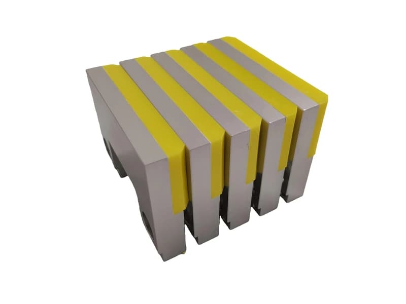
Covered contact faces and exposed metal interfaces for fit review.
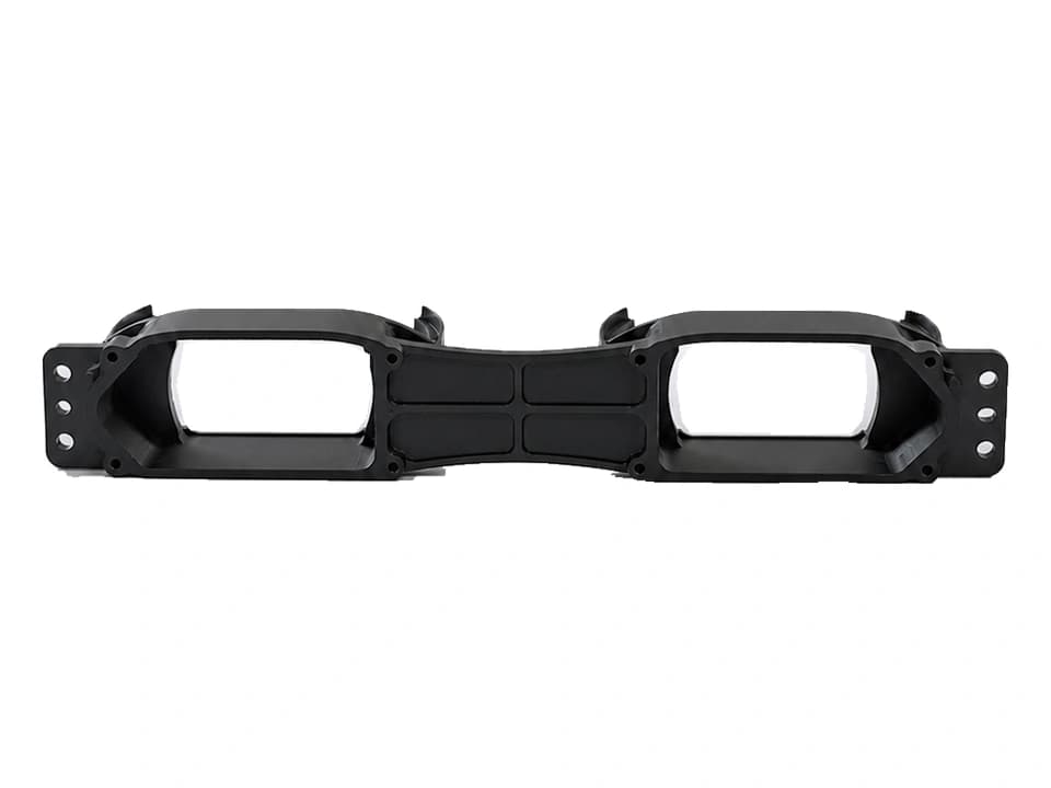
Twin viewing openings, central bridge and mechanical interface geometry.
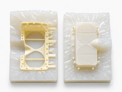
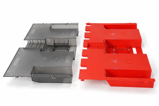
Two complementary silicone mold halves reveal the housing cavity and alignment features.
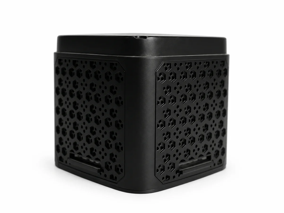
Perforated enclosure geometry and exterior appearance evaluation.
Industrial Metal & Polymer 3D Printing for Complex Geometries and Rapid Testing
| Technology | Max build size (mm) | Max build size (inches) | Lead times from | Layer thickness | Quantity | Prototyping applications | End-use applications |
|---|---|---|---|---|---|---|---|
| SLA | 1600 × 750 × 600 | 62.99 × 29.53 × 23.62 | 2 days | 50–100 μm (0.05–0.1 mm) | 1–500 | High detailed parts with excellent surface quality | Aesthetic parts with high resolution for indoor applications |
| SLS | 550 × 550 × 850 | 21.65 × 21.65 × 33.46 | 2 days | 100 μm (0.1 mm) | 1–10,000 | Durable parts for form, fit and function testing | Batch production of functional, high strength parts |
| SLM | 355 × 405 × 400 | 13.98 × 15.94 × 15.75 | 4 days | 20–80 μm (0.02–0.08 mm) | 1–1,000 | Metal prototypes with complex geometries | Functional and lightweight metal components |
| FDM | 320 × 320 × 325 | 12.60 × 12.60 × 12.80 | 1 day | 200 μm (0.2 mm) | 1–1,000 | Quick proof of concept models | Spare parts and jigs and fixtures |
| MJF | 377 × 277 × 380 | 14.84 × 10.91 × 14.96 | 3 days | 80 μm (0.08 mm) | 1–50,000 | Functional and high-fidelity prototypes | Higher volume production and functional parts |
| LCD | 353 × 196 × 350 | 13.90 × 7.72 × 13.78 | 4 days | 20–80 μm (0.02–0.08 mm) | 1–1,000 | High detailed parts with excellent surface quality | Higher volume production and functional parts |
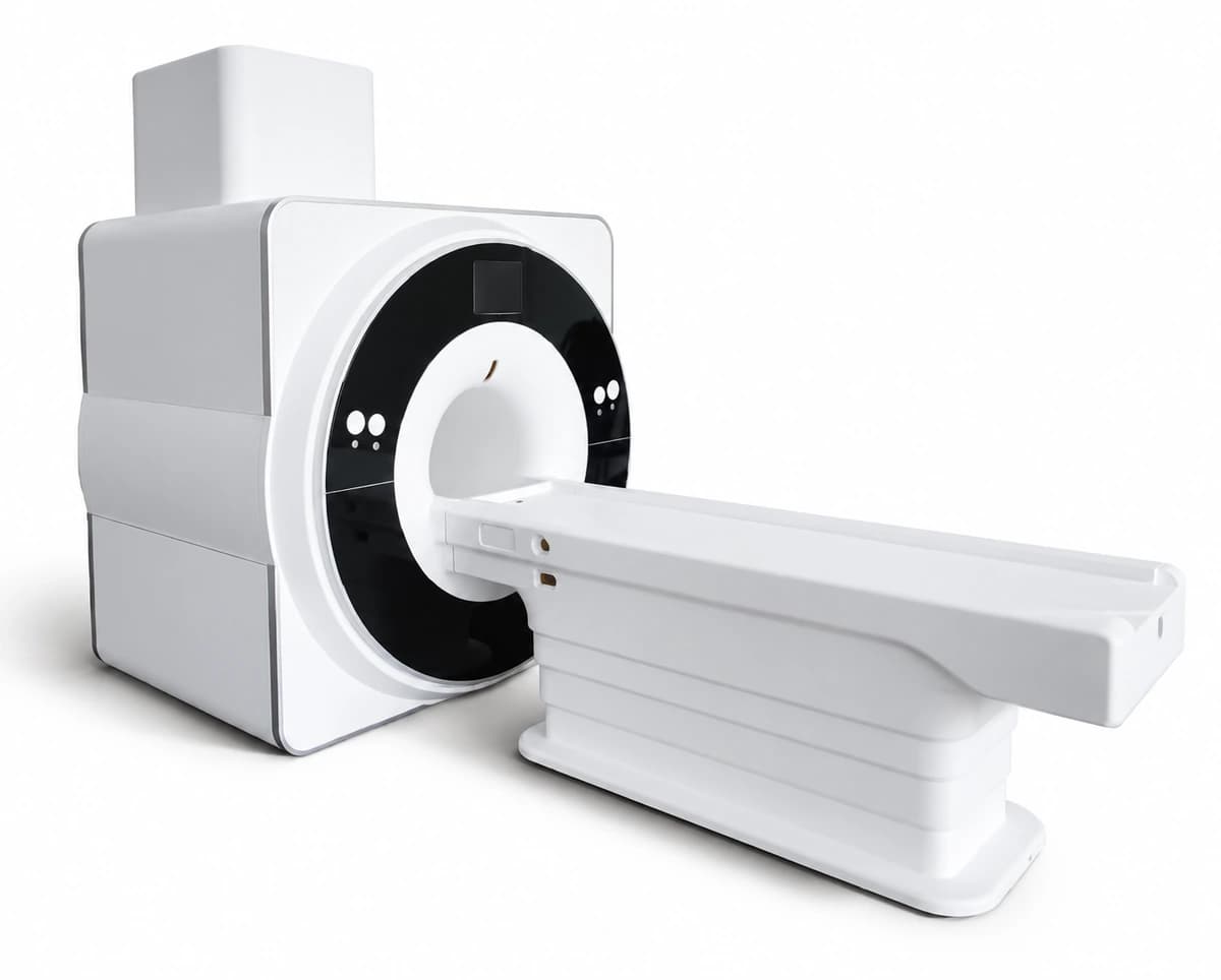
Resin-printed equipment model for geometry and appearance evaluation.
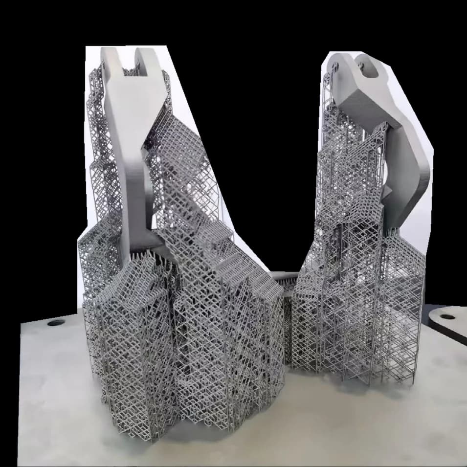
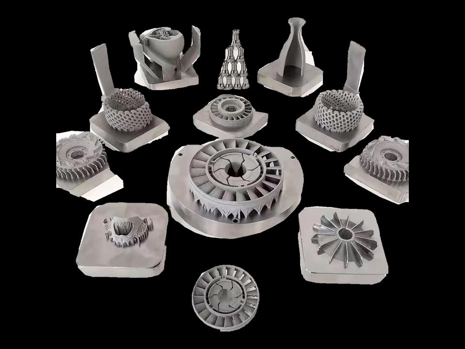
Metal additive components with visible support and lattice features.
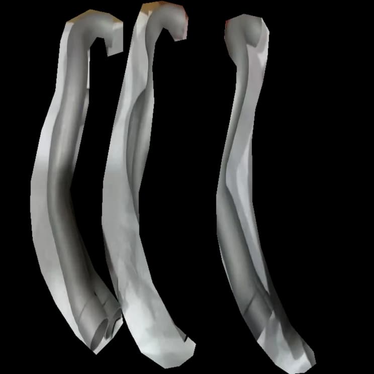
Complex curved tubular geometry produced by metal additive routes.
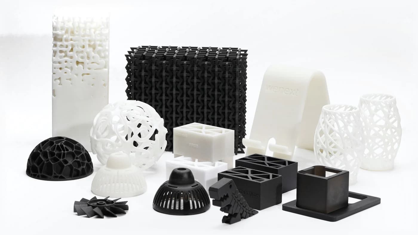
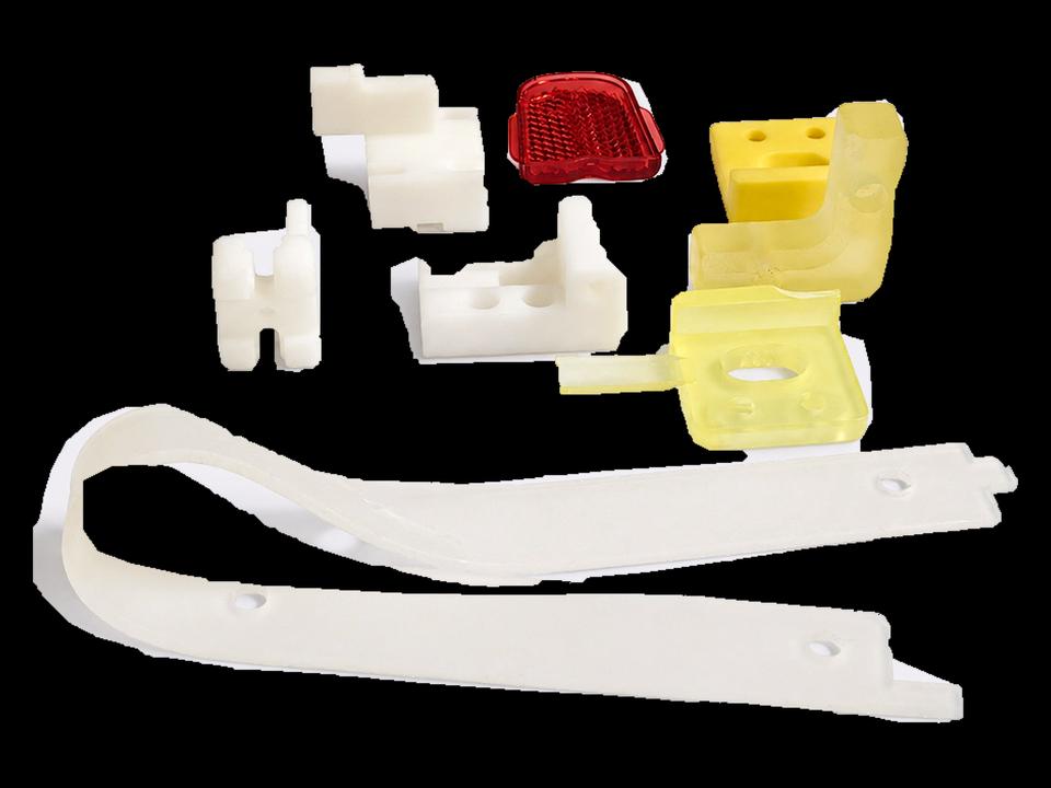
Lattice forms, complex shapes and polymer prototype housings.
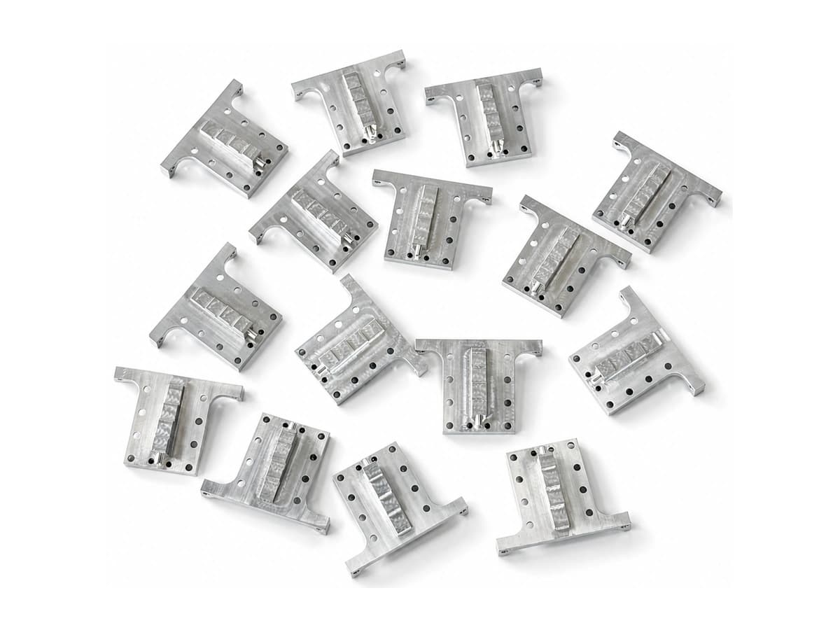
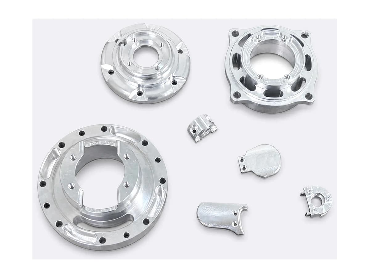
Plan pilot runs, design iterations and bridge quantities around an agreed revision, manufacturing route and inspection scope.
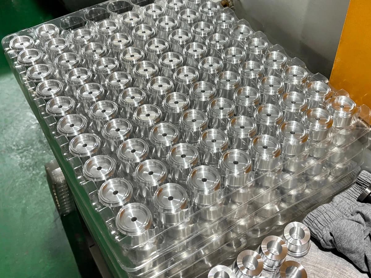
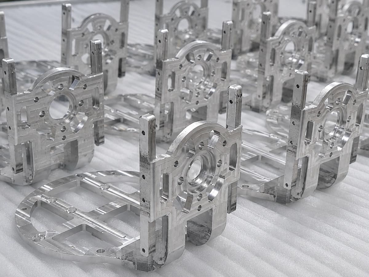
Move a stable design toward repeat manufacturing with process consistency, production inspection and batch quality controls.
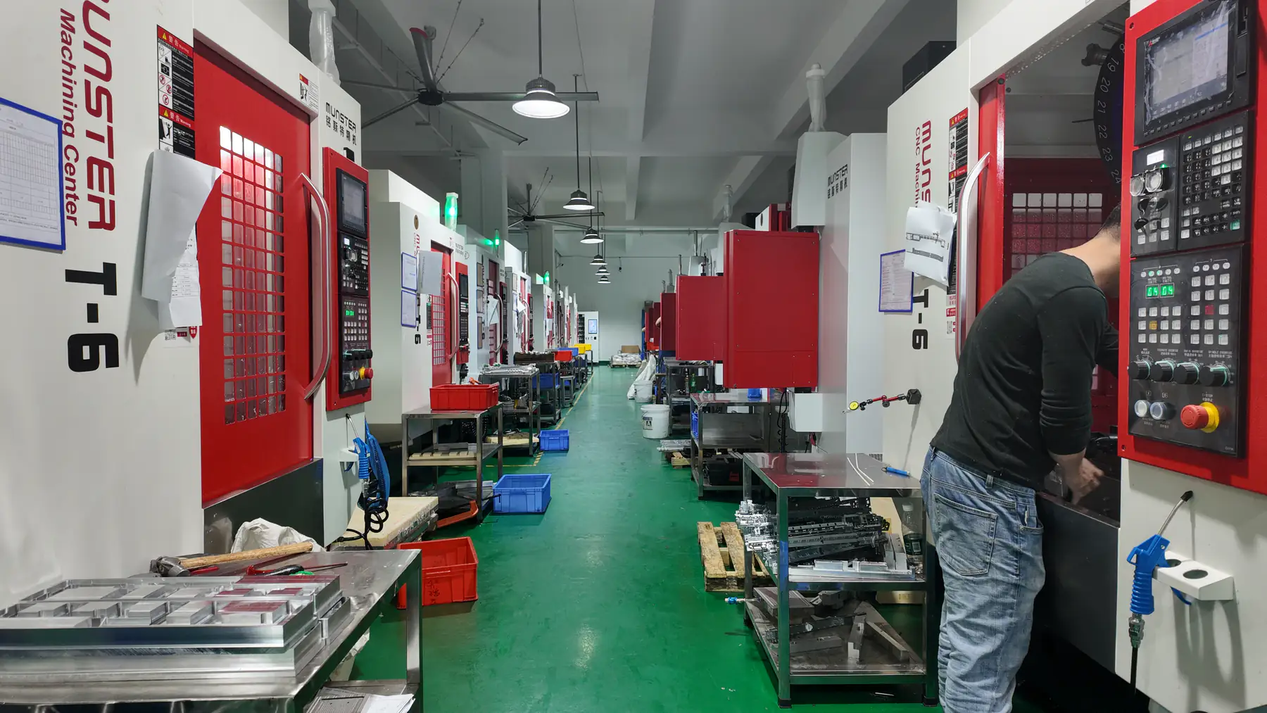
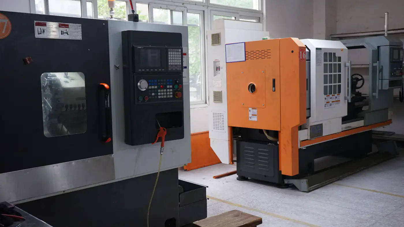
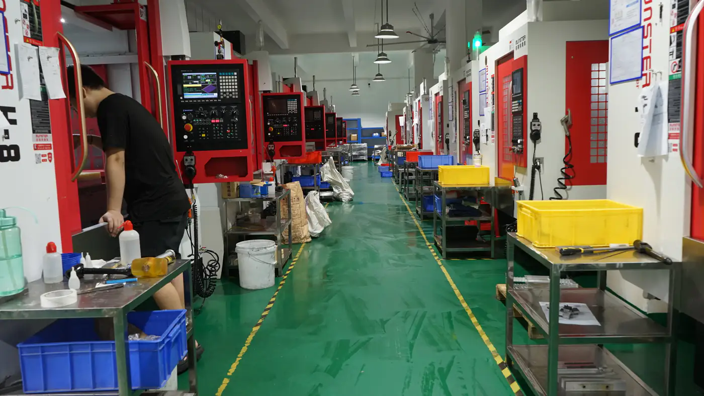
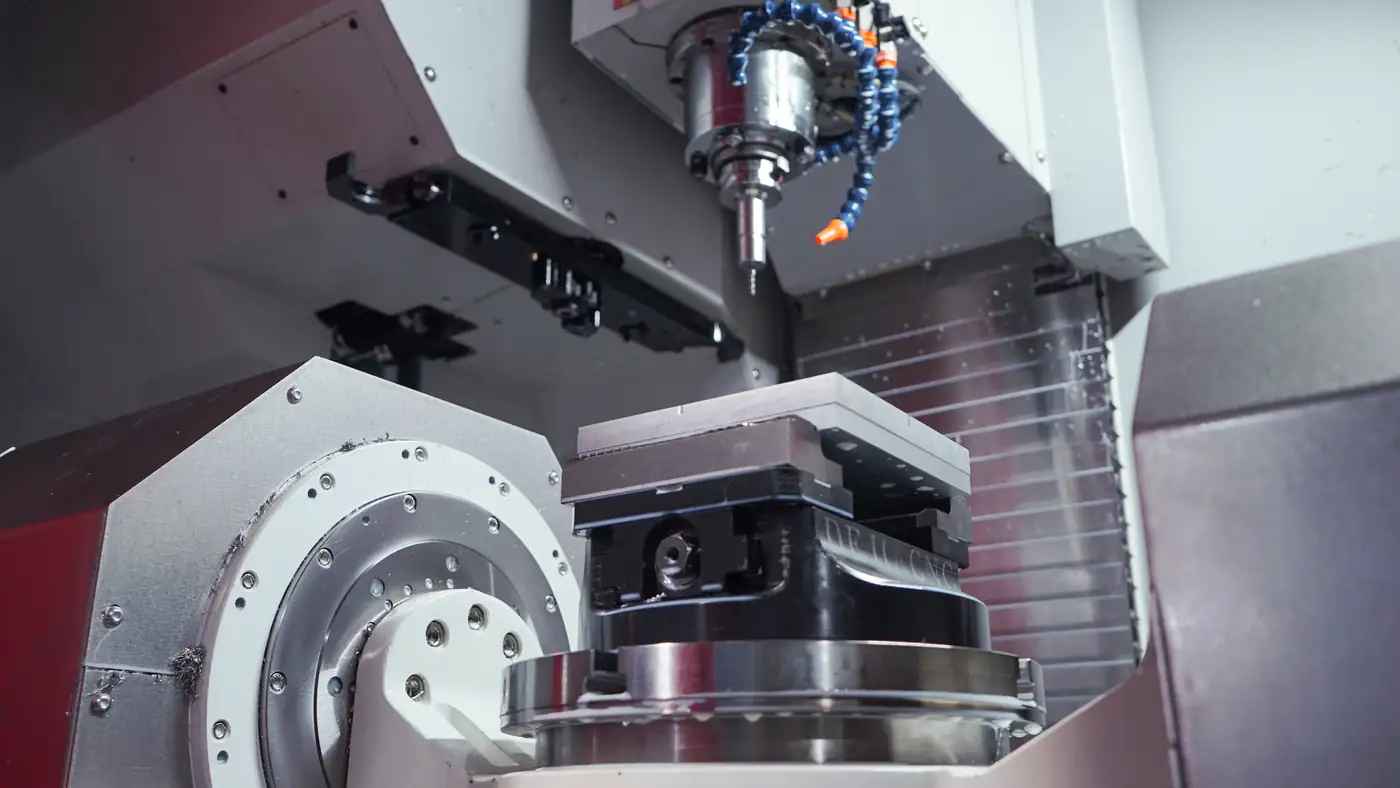
Quality management follows the existing ISO 9001 / ISO 13485 manufacturing scope. Part-specific inspection and documentation are agreed during engineering review.
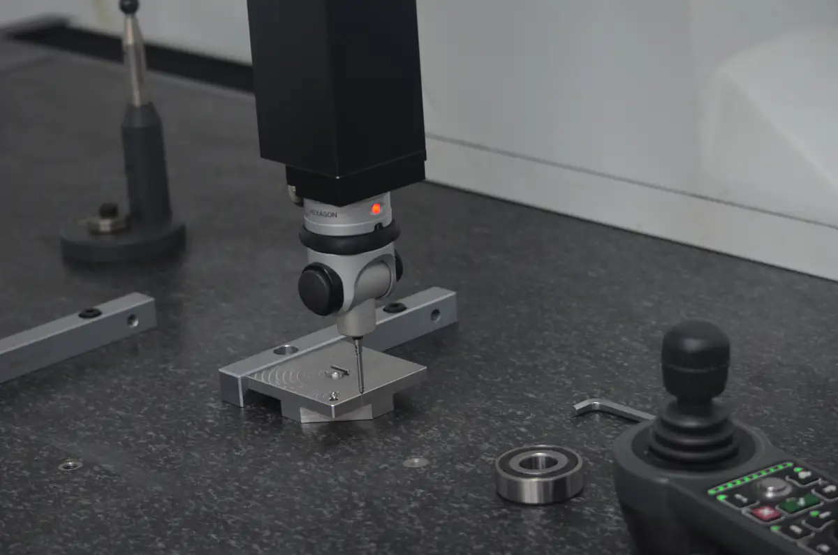
Review supplied material identification and project-specific requirements before manufacturing.
Check agreed features during machining and assembly to support the approved manufacturing route.
Inspect drawing-defined dimensions and interfaces using a suitable method and datum strategy.
Review completed geometry, surface condition and agreed acceptance requirements.
Agree the required inspection records and documentation scope during quotation.
Final tolerances and inspection methods depend on the part, material, drawing requirements and engineering review.
Upload your CAD drawings and project requirements. Our engineering team will review manufacturability, materials, tolerances, and production requirements.