
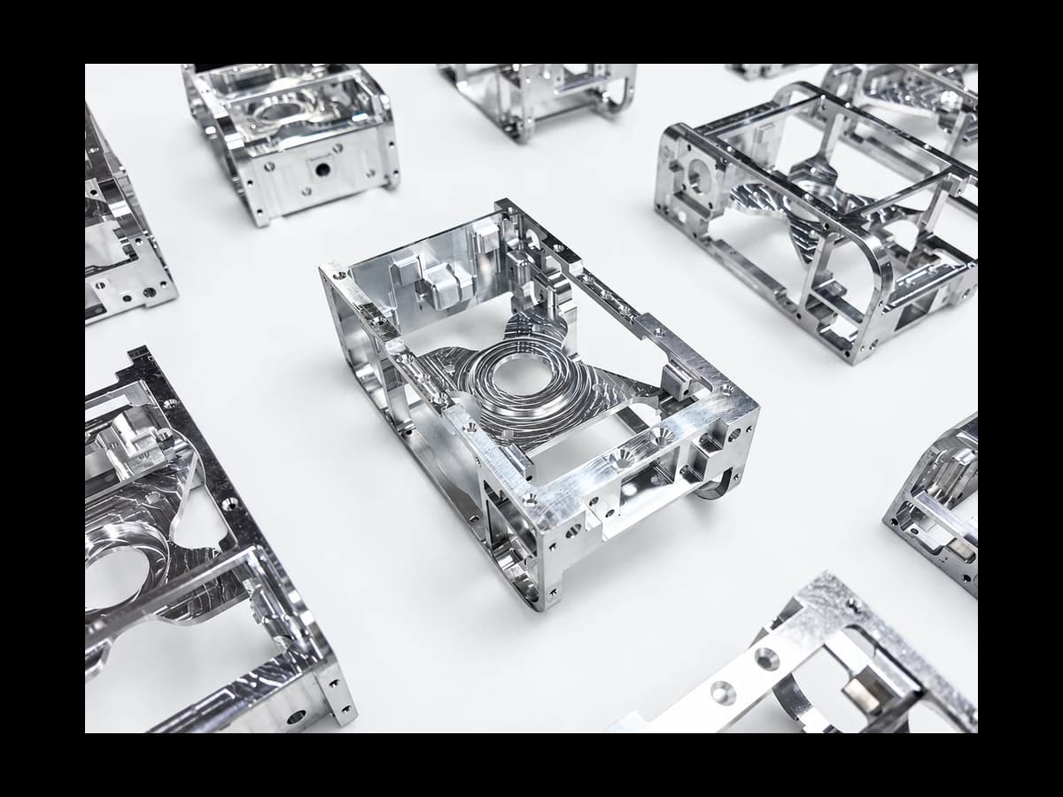
A CNC-machined aluminum housing is more than a protective box. It may locate a circuit board, hold a bearing, seal an optical assembly, support a connector, or transfer heat to another component. Each function affects how the part should be designed, machined, inspected, and quoted.
A housing that looks straightforward in CAD can become costly when it combines deep pockets, thin walls, tight internal corners, difficult workholding, and tolerances applied more broadly than necessary. Those same design choices can also create uncertainty for purchasing teams comparing suppliers.
This guide connects design for manufacturability (DFM) with the information buyers need for a reliable CNC aluminum housing quotation. It covers geometry, 6061 versus 7075 material selection, GD&T, anodizing, cost drivers, and a practical RFQ checklist.
The central principle: Define the features that make the housing function, give the manufacturer reasonable access to produce them, and describe how the finished part will be accepted.
1. Start With the Housing's Function, Not the Toolpath
Before optimizing a machined enclosure, establish what it must do in the final assembly. A cover that only protects electronics has different priorities from a housing that also locates precision shafts, carries structural loads, or seals against moisture.
Identify the functional interfaces first. These may include mounting faces, bearing seats, connector cutouts, threaded inserts, gasket grooves, alignment pins, optical openings, or thermal contact surfaces. Mark which interfaces must relate accurately to one another and which exterior surfaces are primarily cosmetic.
For example, a connector opening may need a tightly controlled position relative to PCB mounting holes, while a non-mating exterior wall may not. Giving both features the same stringent tolerance can increase inspection and manufacturing effort without improving assembly performance.
The sourcing implication is equally important: a supplier cannot reliably evaluate the critical features from appearance alone. Provide an engineering drawing or equivalent controlled product definition that communicates the function behind the geometry.
2. Five DFM Decisions That Shape Machinability
Wall thickness: consider unsupported height and clamping
Thin housing walls may deflect under cutting forces, vibrate during machining, or move when clamping pressure is released. The risk depends on more than nominal wall thickness: wall height, span, material, pocket geometry, tool engagement, and fixture support also matter.
If a thin wall is necessary for weight or packaging, identify it as a design requirement instead of assuming it is a routine feature. A manufacturer may need a modified machining sequence, additional support, lighter finishing passes, or a different workholding approach. These measures should be reviewed against the drawing, not treated as guaranteed fixes.
DFM question: Which walls must remain thin for product function, and which can be reinforced or shortened without affecting the assembly?
Internal corners: leave space for the cutting tool
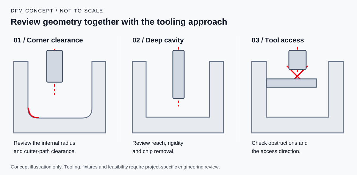
A conventional rotating end mill cannot produce a perfectly sharp internal vertical pocket corner. The cutter leaves a radius, and smaller cutters typically require more delicate, time-consuming machining when used in deep cavities.
A larger internal corner radius can allow a more practical cutter and smoother tool movement. The corner also needs enough clearance for the toolpath: merely matching the drawn radius to the cutter radius can still make cornering inefficient. If a square mating part must fit into the pocket, a local corner-relief feature may be more economical than specifying a fully sharp corner—provided the relief does not interfere with the design.
DFM question: Does the assembly truly need a sharp corner, or does it only need clearance for a square mating component?
Deep pockets: account for reach, chips, and remaining material
Deep cavities can require long-reach tools, additional machining time, careful chip removal, and staged roughing and finishing. Long tool overhang may reduce rigidity, while removing a large amount of aluminum can release residual stresses and change the shape of the remaining walls.
For a housing with multiple cavities, consider whether the floor depth is functionally necessary, whether the opening permits tool access, and whether every internal surface needs the same finish. Accessible datum and clamping surfaces should be planned before most of the stock is removed.
A five-axis strategy may improve access to angled features or reduce some reorientations, but it is not automatically faster or less expensive than a simpler setup. The correct approach depends on geometry, fixturing, quantity, and machine capability.
DFM question: Can the required functional space be achieved with a shallower pocket, a different access direction, or a revised machining sequence?
Holes, threads, and mounting bosses: design for assembly
Hole location, drill entry, thread specification, and tool clearance can be more important than the number of holes. A drilled feature near an edge or intersecting a cavity may require special planning. Deep blind threads, inaccessible counterbores, and closely spaced mounting bosses can also complicate machining and inspection.
Specify the thread standard, size, depth or engagement requirement, and whether inserts are permitted. Distinguish a clearance hole from a precision-locating hole. If the housing supports a gasket or connector, define the relevant flatness and position requirements on the drawing.
DFM question: Is each hole defined by the assembly it serves, including the mating fastener and inspection requirement?
Datums and setups: make the part locatable
A machinist needs a repeatable way to hold and measure the housing. Stable datum faces and accessible reference features can reduce uncertainty between operations. A cavity-heavy design that removes every convenient gripping surface early in the process can make later features more difficult to position consistently.
Discuss the intended datum scheme early, especially when the housing has features on several faces. More setups are not always avoidable; the objective is to control how reference features carry through them.
DFM question: After the first machining operation, how will the remaining critical features be located and inspected?
3. 6061 vs. 7075 Aluminum for CNC Housings
Choosing an alloy should begin with the service conditions, not the assumption that a stronger grade is always better. 6061-T6 or 6061-T651 is often a practical candidate for general-purpose enclosures. 7075-T6 or 7075-T651 can be appropriate when higher strength is justified by the design. The final choice depends on loading, corrosion exposure, joining, finishing, stock availability, and cost.
| Decision factor | 6061-T6 / T651 | 7075-T6 / T651 |
|---|---|---|
| Typical use in housing design | General-purpose structural and equipment housings | More highly loaded, weight-sensitive components where added strength is valuable |
| Strength | Lower than 7075 in the compared tempers | Higher typical yield and tensile strength |
| Stiffness | Elastic modulus is broadly similar to 7075 | Greater strength does not mean a proportional increase in elastic stiffness |
| Corrosion and joining | Often advantageous where corrosion performance or welding matters | Requires more careful review of corrosion protection and joining method |
| Sourcing decision | Evaluate standard stock forms, finishes, and cost | Confirm that the extra strength justifies material and processing trade-offs |
Do not use generic online property tables as acceptance criteria. Material properties depend on the alloy, temper, product form, thickness, orientation, and governing specification. A released drawing should specify the required material and any permitted substitution; purchase documentation should define whether mill test records are required. Kaiser Aluminum’s published 6061 and 7075 technical sheets are useful reference points, not substitutes for a project-specific material specification.
For heavily pocketed housings, also discuss starting stock and stress condition. Residual stress and the amount of material removed can affect dimensional stability regardless of which alloy is chosen.
Buyer decision: If the housing is limited mainly by elastic deflection, changing from 6061 to 7075 alone may offer little benefit; geometry and support may matter more. If it is strength-limited, evaluate the appropriate alloy and temper against the actual load case.
4. Tolerances and GD&T: Control the Features That Matter
A functional CNC aluminum housing rarely needs its tightest tolerance applied everywhere. The more useful approach is to identify which surfaces establish the part in the assembly and which dimensions govern fit, alignment, sealing, and interchangeability.
Consider a housing that mounts to a baseplate and locates a connector. Its mounting plane may be the primary datum, a side face or feature may control orientation, and a suitable locating feature may establish the remaining position. The actual datum scheme must reflect the assembly and inspection method—not a generic drawing template.
Where applicable, use ASME Y14.5 conventions to define position, profile, flatness, perpendicularity, and other geometric controls. These specifications communicate design intent more reliably than unexplained notes such as “high precision throughout.”
Inspection requirements should be equally specific. Decide whether critical interfaces need dimensional reports, a first-article inspection, CMM measurement, material certification, or a customer-approved inspection plan. Do not assume every supplier includes every report in its standard quote.
Buyer decision: Identify the measurements that determine acceptance and agree on their inspection stage, including whether dimensions are checked before or after finishing.
5. Anodizing and Surface Finishing: Design for the Finished Part
Anodizing can improve the surface performance or appearance of an aluminum enclosure, but it is not dimensionally neutral. The process converts aluminum at the surface into an oxide layer. Some of that layer extends beyond the original surface, so the final sizes of bores, grooves, mating faces, and threads can change.
The dimensional effect varies with alloy and anodizing conditions, as described in the Aluminum Anodizers Council’s technical FAQ. Do not apply a universal coating-growth allowance to every feature. Instead, tell the machining and finishing suppliers which interfaces are dimension-critical and whether the print dimensions apply after finishing.
For mating bores, threaded features, electrical contact points, gasket faces, or tight assemblies, discuss masking, plugging, or the approved finishing method. When appearance matters, specify color, sheen, cosmetic acceptance criteria, and whether a finished sample is needed. The distinction between conventional decorative anodizing and hardcoat applications should be agreed before the quotation is finalized.
Finishing should be part of the DFM discussion—not a purchase-order detail added after machining is complete. A part may meet its as-machined dimensions but fail to assemble once the surface treatment has been applied.
Buyer decision: State the finish specification, any masking areas, and the required condition of critical dimensions at final acceptance.
6. What Actually Drives CNC Aluminum Housing Cost?
The quoted price reflects more than the weight of the finished enclosure. It includes starting stock, machining time, machine and fixture setup, tooling, finishing, inspection, documentation, and the supplier's delivery requirements.
| Cost driver | Why it matters | Useful buyer action |
|---|---|---|
| Large pockets and high material removal | More stock, cutting time, and potential distortion control | Distinguish necessary cavities from optional weight-saving features |
| Deep, narrow access features | Longer tools, slower cutting, or a revised approach | Allow workable tool access and internal radii |
| Features on multiple faces | May require additional setups and verification | Identify critical relationships and consider machining access early |
| Unnecessarily tight tolerances | Increase process control and inspection effort | Tolerate functional interfaces appropriately; relax noncritical ones when permitted |
| Finish and masking requirements | Add operations and may affect final dimensions | Specify complete finishing and acceptance requirements |
| Quantity and repeat orders | Setup effort is spread across differing quantities | Request prototype, initial-batch, and repeat-volume pricing separately |
For example, two suppliers may quote the same model differently because one includes finished-part inspection and anodizing while another prices machining only. Similarly, a prototype unit price should not be treated as the unit price for a recurring production order without reviewing setup and quantity assumptions.
Cost reduction should never mean relaxing critical fit or safety requirements without engineering approval. It means removing complexity that does not contribute to the product's intended function.
7. What Should US Buyers Send With an Aluminum Housing RFQ?
A useful request for quotation gives the supplier enough information to evaluate both the geometry and the commercial scope. Submit a readable 3D model together with a controlled 2D drawing or equivalent complete product definition. The model describes shape; the drawing communicates the specifications that are not reliably conveyed by geometry alone.
CNC Aluminum Housing RFQ Checklist
When comparing quotations, make sure each supplier is pricing the same revision, quantity, finish, inspection scope, and shipping assumptions. Ask suppliers to identify exclusions or proposed design changes in writing. That makes cost and lead-time differences easier to interpret.
A supplier may also recommend a radius change, an alternate stock condition, a different setup, or a more targeted inspection plan. Evaluate those suggestions against the functional requirements rather than accepting or rejecting them solely on unit price.
8. From Prototype to Repeat Production
An effective route starts with a DFM review of the CAD and drawing. The first prototype can then validate tool access, critical interfaces, assembly fit, finishing requirements, and inspection methods. Any accepted changes should be incorporated into a controlled drawing revision before a repeat order is released.
For a housing with deep cavities or multi-face features, the prototype is particularly useful for reviewing workholding and dimensional stability. The same checks should carry into the production plan: agreed datum references, inspection points, finishing sequence, and revision control.
Frequently Asked Questions
Can a CNC-machined aluminum housing have perfectly sharp internal corners?
Conventional end milling leaves a radius at internal vertical corners. A design requiring a square mating component may use a suitable relief feature or a different manufacturing approach, subject to geometry, access, and supplier review.
What is a practical minimum wall thickness for a CNC aluminum enclosure?
There is no universal value that applies to every housing. Feasibility depends on wall height and span, alloy, local geometry, workholding, machining sequence, and dimensional requirements. Share the drawing for an application-specific DFM assessment.
Should I choose 6061 or 7075 for an enclosure?
6061 is often a good starting point for general-purpose housings. Consider 7075 when additional strength is justified and corrosion, joining, finish, and procurement considerations are acceptable. Confirm the required temper and stock form rather than specifying an alloy number alone.
Can anodizing change the size of holes or threaded features?
Yes. Anodizing forms an oxide layer that can change finished dimensions. Define critical post-finish fits and discuss coating, masking, or other approved treatment with the manufacturing and finishing teams.
Do I need both a 3D CAD model and a 2D drawing for a CNC housing quote?
Providing both is useful. CAD communicates geometry, while a drawing conveys datums, tolerances, thread specifications, finishing, notes, and inspection expectations. If an alternative controlled product definition is used, make sure those requirements are still unambiguous.
Ready to Review Your Aluminum Housing Design?
A clearer housing design leads to a clearer manufacturing discussion. If you are sourcing a CNC-machined aluminum enclosure, share your CAD model, drawing, material and temper, quantities, critical features, and finish requirements with HERUIYUN.
Our team can review your project requirements and assess manufacturing considerations before preparing a project-specific quotation. Feasibility, tolerances, processes, and delivery are confirmed for each project—not assumed from a general guide.
You can also explore our CNC milling services and five-axis machining capabilities when evaluating the best approach for your housing.