
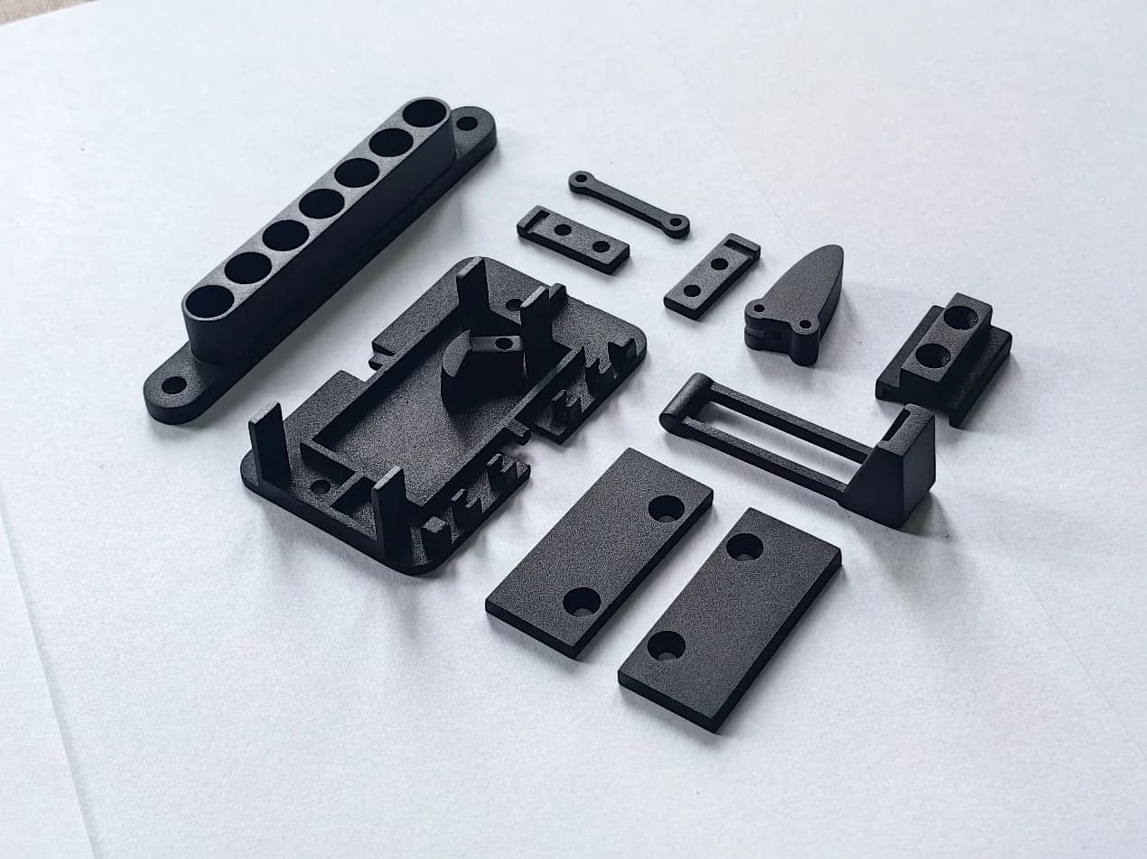
When a printed blank makes sense
Combining 3D printing with CNC machining can expand the options available during prototype development. Additive manufacturing creates the initial blank; subtractive machining then refines selected surfaces and interfaces. The route is useful when neither process alone meets the design objective efficiently.
The starting point is the geometry. The source examples include undercuts beyond the reach of a conventional T-slot cutter, semi-enclosed cavities, curved internal channels and spatially curved holes. These features may justify printing the blank, while the features selected for CNC finishing must remain accessible to the tool. An internal feature that is difficult to machine does not become accessible simply because the blank was printed first.
The blank must also be practical to hold. A part with no stable reference, no accessible gripping feature and a fully free-form exterior can be difficult to fixture without marking or distorting it. Clamping needs to be considered before printing, rather than improvised after the finished blank arrives.
Quantity, size and surface requirements
Prototype and small-batch work are natural candidates for a hybrid route. The source discussion considers quantities of 1 to 100 pieces, but this is a planning example rather than a fixed production or pricing limit. Part weight, print time, setup work, inspection and any repeat operations all affect the comparison with machining from conventional stock.
Large or heavy blanks deserve particular attention. A reduction in the amount of material removed by CNC does not automatically produce a lower total cost. Printing, support removal, preparation, fixturing and finishing can add enough work to outweigh the saving in machining stock.
Appearance is another reason to consider CNC finishing. Cutting selected as-built surfaces can remove irregularities and prepare a part for suitable surface-finishing processes. The source notes mention Ra 3.2 as a possible surface target. It should be treated as a project requirement to agree and inspect, with its unit and measurement conditions confirmed, rather than a guaranteed result for every printed material or geometry.
Start with a stable printed blank
Printing variation affects the next operation. Even parts from one machine or build can differ, so the machining plan should consider the actual condition of the blanks rather than assuming that every printed feature matches the CAD model exactly.
The original discussion highlights machine stability, the printing environment and consistency of the feedstock. Temperature and humidity controls need to suit the selected resin or powder process. Material handling, storage and transport also belong in the review, alongside reliable power and a workshop foundation protected from disruptive vibration.
These are connected manufacturing controls. A fixture cannot compensate for an unsuitable blank, and a good print cannot compensate for a poor datum strategy. Inspect the reference features and the regions to be machined before deciding how to locate and hold the part.
Plan machining allowance during DFM
Add machining stock only where the secondary operation needs it. During a manufacturability review, identify the surfaces to finish, the reference geometry and the allowance required to absorb printing variation without removing a wall or losing a critical feature.
The source notes use dimensional-variation examples of ±0.2% for SLA, ±0.5% for FDM and ±0.25% for SLM, together with roughly 1 mm of stock per side in a hybrid machining example. These figures are discussion inputs, not universal process tolerances or a standard HERUIYUN allowance. The process, material, size, orientation and supplier capability must be reviewed before they are used on a drawing or quotation.
A local allowance must also be checked against the final geometry. Adding stock to a mating surface can be sensible; adding it blindly to every feature can make tool access, clamping or material removal harder. The printed blank and the CNC operation should be planned as one route.
Choose a workable fixture
A vice is the simplest option when the printed blank has a suitable square or rectangular base. That base provides a regular gripping feature for secondary machining, provided the clamping force and contact surfaces suit the part.
An internal expanding mandrel may be useful when a regular external base is unavailable but a suitable hole can be used for location. Its suitability depends on the condition and strength of the printed feature, the required accuracy and the cutting load; expansion alone is not a guarantee of stable location.
If the blank has neither a usable hole nor a regular base, the design may need a dedicated clamping base. Such a feature should be agreed during DFM, including how it will be removed and how the final surfaces will be inspected. The purpose is to create a controlled manufacturing reference without compromising the intended part.
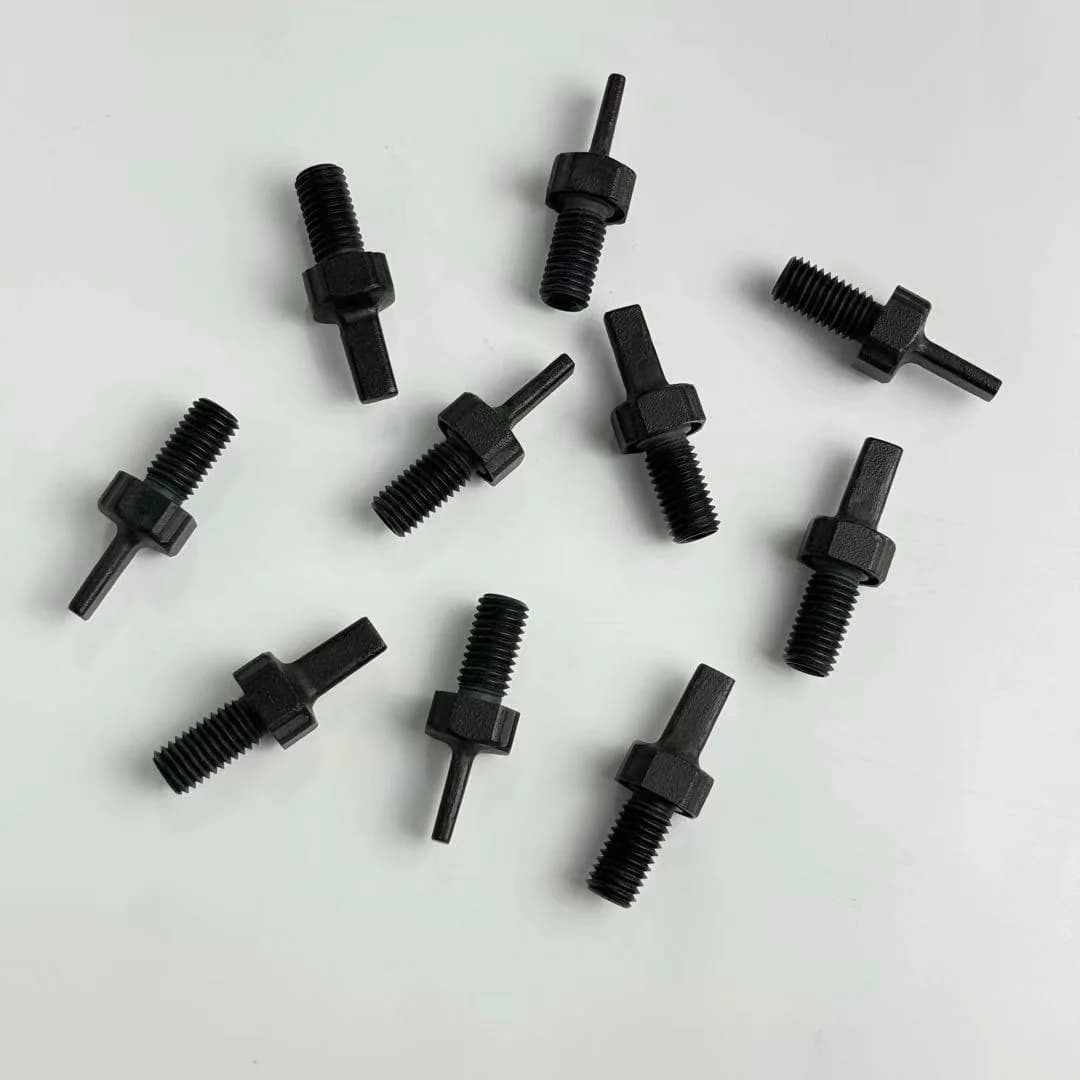
One route to expand manufacturing options
Printing followed by CNC machining is a manufacturing option, not a promise of a flawless result. It works best when the design needs an additive feature and the team can define a credible plan for the blank, the fixture, the cutting operation and the final inspection.
The broader idea is familiar: CNC machining can follow an initial shaping process, including extrusion, die casting, forging or forming. The useful question is which sequence supports the part's engineering objective. For a printed blank, review the complete route and compare it with other low-volume manufacturing options.
The related UK watch designer discussion explores why a designer may retain an additive feature even when it makes finishing more involved. To review a specific part, share the drawing and manufacturing requirements, including the surfaces, fits and appearance that matter most.