Machined Geometry
Pocketed blocks, drilled holes and machined reference faces.
Machined tooling supports with pocketed blocks, fixing holes and reference faces. Review support height and contact geometry against the part or fixture being supported.
Upload CAD Drawings for a Quote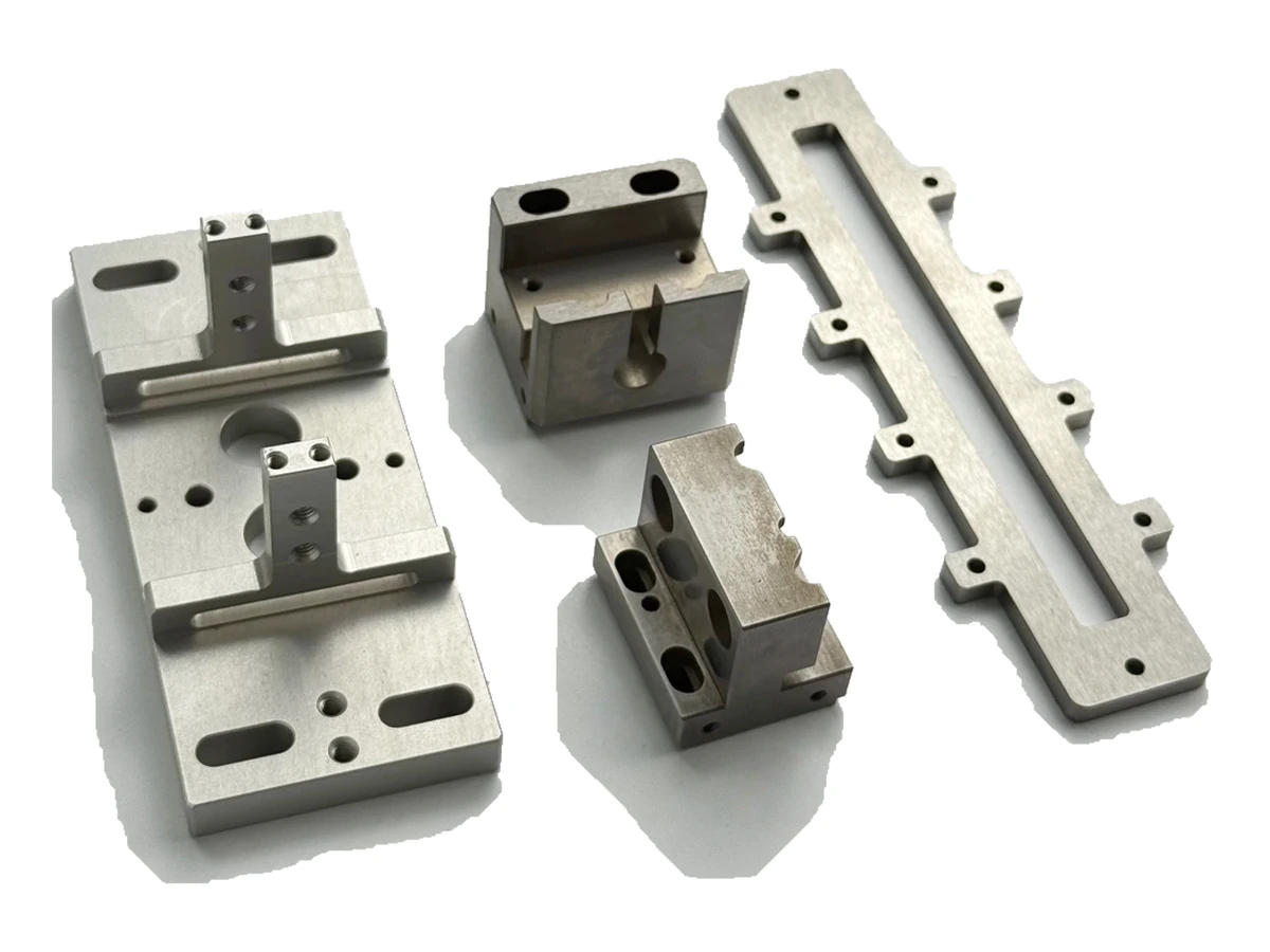
Pocketed blocks, drilled holes and machined reference faces.
Define support height, hole position and mating clearances.
Identify load-contact and clearance surfaces and define the support's installed orientation.
Coordinate hole positions, mating faces and assembly access. Any stiffness or load requirement needs a separate drawing and validation scope.
Plan the reference faces and fixing features so the support's working height remains traceable across setups. Pocket access and clamping need to preserve the seating surfaces used in the assembled tooling.
For machined tooling supports, specify the alloy, condition and finish on the drawing. Review the finished interfaces, treatment sequence and inspection requirements before selecting this candidate material.
For machined tooling supports, specify the alloy, condition and finish on the drawing. Review the finished interfaces, treatment sequence and inspection requirements before selecting this candidate material.
For machined tooling supports, specify the alloy, condition and finish on the drawing. Review the finished interfaces, treatment sequence and inspection requirements before selecting this candidate material.
For machined tooling supports, specify the alloy, condition and finish on the drawing. Review the finished interfaces, treatment sequence and inspection requirements before selecting this candidate material.
These grades are engineering selection candidates, not a statement of stock availability or verified capability for every material condition. Material, heat treatment and inspection requirements are subject to factory confirmation against the drawing.
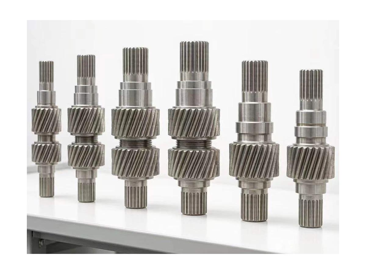
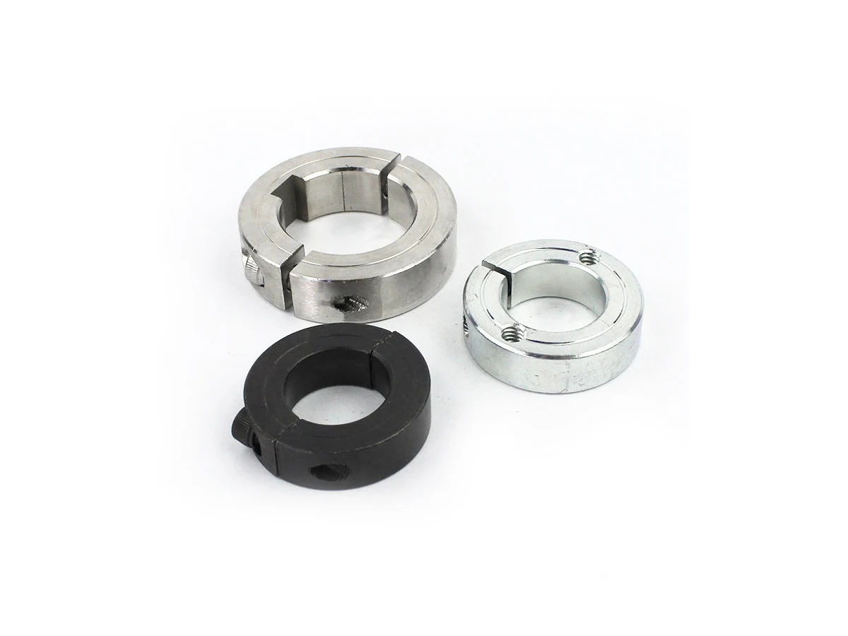
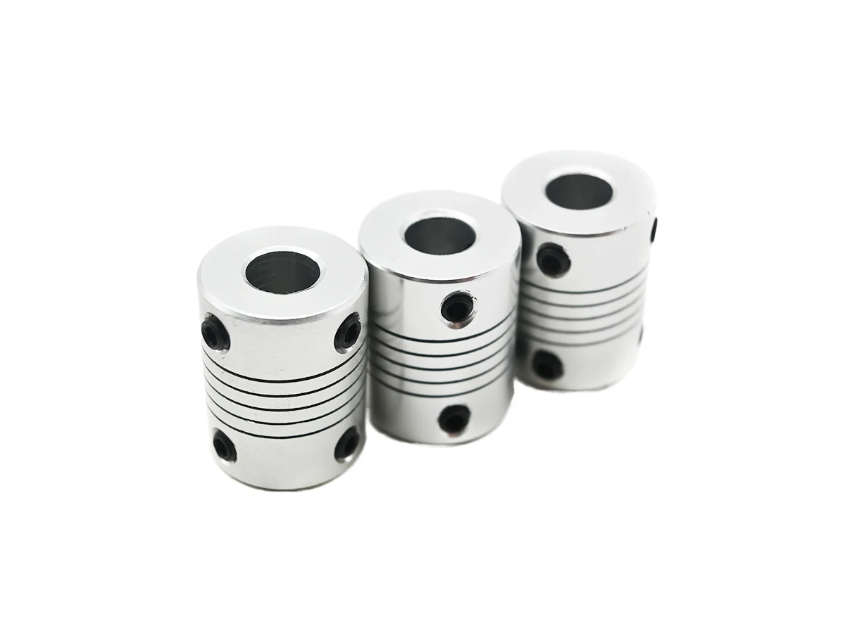
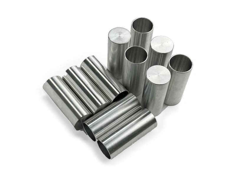
Explore CNC Metals & MaterialsUse the dimensioned drawing to define these requirements. Photographs illustrate visible geometry; they do not establish a standard size, material grade or performance rating.
A support can establish height or position during assembly. Define the mating contact and how the support is secured.
Support blocks may sit beneath or beside a workpiece. Review clamp access and the intended force path with the fixture design.
Drawing-defined supports can adapt an existing tooling arrangement. Provide the current fixture interface and required inspection condition.
Use the installed base and working face as functional references for the support height.
Review access to pockets and fasteners when the support is installed.
Define finished contact surfaces and protect them during deburring and treatment.
Agree support-height and fixing-location checks separately from a complete fixture load test.
Send the CAD model and project requirements for manufacturing review.
Upload CAD Drawings for a Quote