Machined Geometry
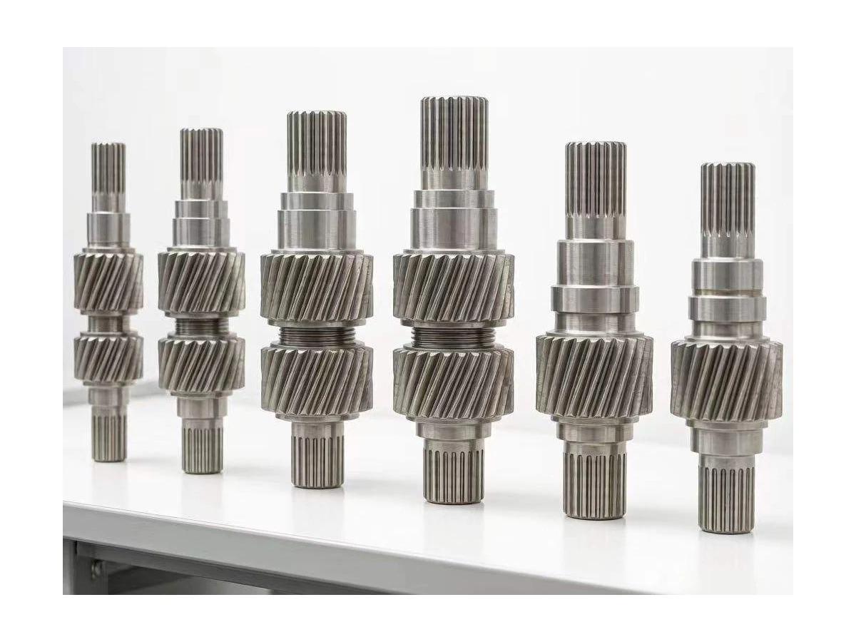
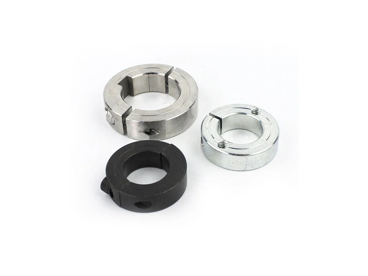
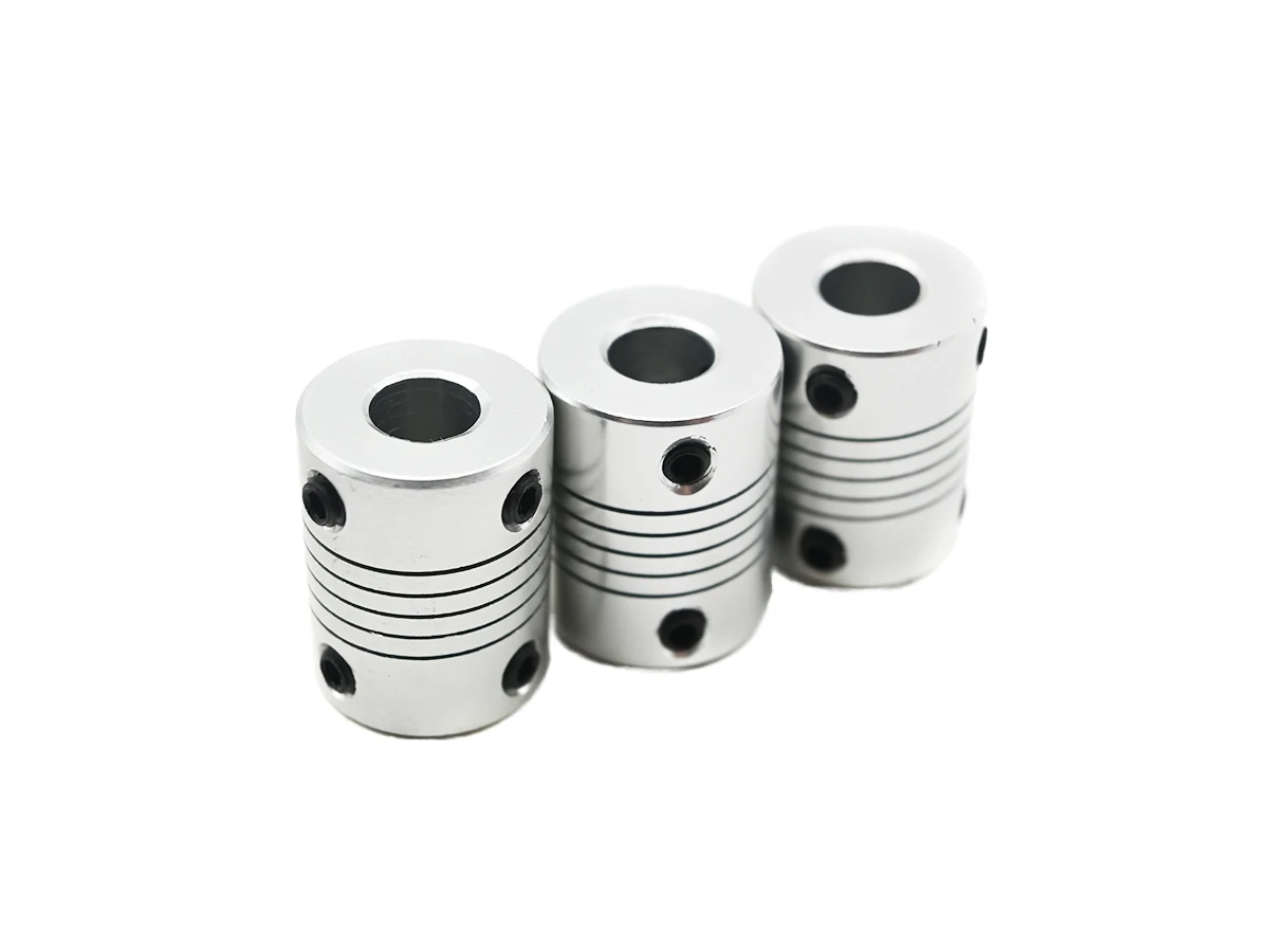
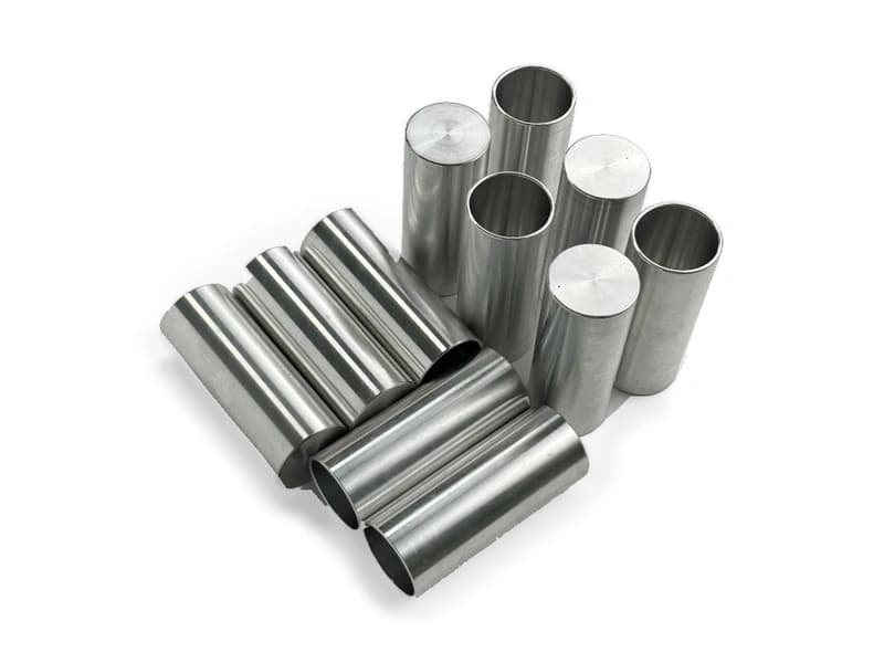
Finned surfaces, semicircular openings and fixing holes.
Finned interface components with semicircular openings and fixing holes. Review the shaped contact envelope and attachment geometry for the actual equipment interface.
Upload CAD Drawings for a Quote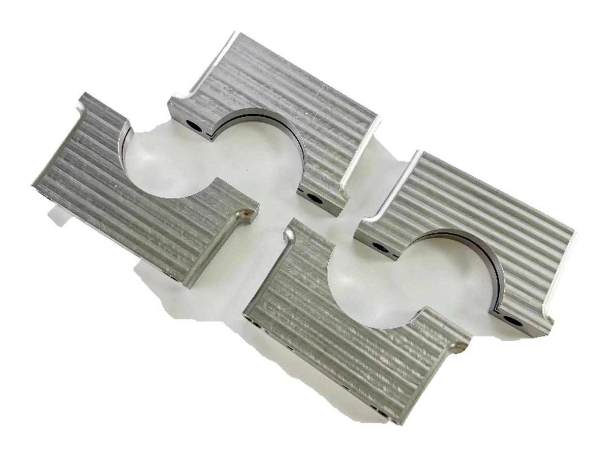
Finned surfaces, semicircular openings and fixing holes.
Review the mating envelope and fastening positions.
Define the semicircular contact geometry, its axis and the mating envelope. Identify clearance and controlled-contact surfaces separately.
Relate the fins and mounting features to the equipment installation. No liquid-cooling, sealing or pressure-test capability is implied.
Review fin access, shaped openings and mounting holes as a combined machining problem. The interrupted sections need a workholding plan that preserves the specified contact and fixing relationships.
For finned interface components, specify the alloy, condition and finish on the drawing. Review the finished interfaces, treatment sequence and inspection requirements before selecting this candidate material.
For finned interface components, specify the alloy, condition and finish on the drawing. Review the finished interfaces, treatment sequence and inspection requirements before selecting this candidate material.
For finned interface components, specify the alloy, condition and finish on the drawing. Review the finished interfaces, treatment sequence and inspection requirements before selecting this candidate material.
For finned interface components, specify the alloy, condition and finish on the drawing. Review the finished interfaces, treatment sequence and inspection requirements before selecting this candidate material.
These grades are engineering selection candidates, not a statement of stock availability or verified capability for every material condition. Material, heat treatment and inspection requirements are subject to factory confirmation against the drawing.
Explore CNC Metals & MaterialsUse the dimensioned drawing to define these requirements. Photographs illustrate visible geometry; they do not establish a standard size, material grade or performance rating.
A shaped opening can locate or clear a cylindrical mating component. Define the intended contact rather than assigning a function solely from appearance.
Fins may share the body with mechanical attachment features. Review the space required for mounting and any surrounding thermal assembly.
Custom interface parts can support prototype installation trials. Supply the mating geometry and separate mechanical checks from thermal or pressure testing.
Base the setup on the shaped interface and its mounting references.
Check access to the opening, fin gaps and recessed fixing features.
Define which surfaces remain controlled after finishing and how delicate edges are handled.
Agree profile and hole-position checks without inferring sealed cold-plate functionality.
Send the CAD model and project requirements for manufacturing review.
Upload CAD Drawings for a Quote