Machined Geometry
Closely spaced parallel fins and a continuous base.
Finned heatsink components with parallel fins and a continuous mounting base. Review the contact surface, fin envelope and attachment geometry against the thermal assembly drawing.
Upload CAD Drawings for a Quote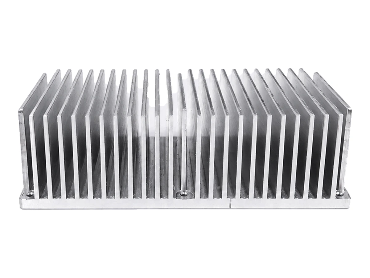
Closely spaced parallel fins and a continuous base.
Define mounting interfaces and the required contact surface.
Define fin height, spacing and the usable base surface. Supply the surrounding airflow and assembly envelope as design inputs.
State required contact flatness and surface finish on the drawing. The reference photo does not establish thermal performance.
Confirm the stock form and manufacturing route for the actual fin geometry before planning base machining and mounting features. Fin spacing, depth and remaining sections affect tool access and handling.
For finned heatsink, specify the alloy, condition and finish on the drawing. Review the finished interfaces, treatment sequence and inspection requirements before selecting this candidate material.
For finned heatsink, specify the alloy, condition and finish on the drawing. Review the finished interfaces, treatment sequence and inspection requirements before selecting this candidate material.
For finned heatsink, specify the alloy, condition and finish on the drawing. Review the finished interfaces, treatment sequence and inspection requirements before selecting this candidate material.
For finned heatsink, specify the alloy, condition and finish on the drawing. Review the finished interfaces, treatment sequence and inspection requirements before selecting this candidate material.
These grades are engineering selection candidates, not a statement of stock availability or verified capability for every material condition. Material, heat treatment and inspection requirements are subject to factory confirmation against the drawing.
Explore CNC Metals & MaterialsUse the dimensioned drawing to define these requirements. Photographs illustrate visible geometry; they do not establish a standard size, material grade or performance rating.
Fins and a contact base can form part of a heat-transfer assembly. Required thermal behaviour must be defined and validated for the complete design.
The base may connect a heat source to a finned body. Review attachment pressure, interface materials and clearances as assembly inputs.
Custom mounting and envelope features can be reviewed during development. Dimensional acceptance is separate from thermal testing.
Select contact and mounting datums that reflect the installed orientation.
Review access between fins and avoid assuming inaccessible features can be machined.
Specify handling, deburring and finish requirements without damaging fin edges.
Agree the requested contact-surface and mounting checks; no universal thermal rating is claimed.
Send the CAD model and project requirements for manufacturing review.
Upload CAD Drawings for a Quote