Machined Geometry
Concentric bore steps and a face-hole pattern.
Machined flanges with stepped central bores and a face-hole pattern. Review bore seating, the mounting face and bolt access as a connected mechanical interface.
Upload CAD Drawings for a Quote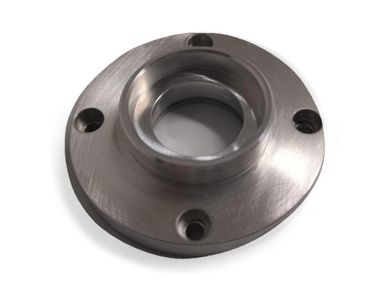
Concentric bore steps and a face-hole pattern.
Relate the central bore and bolt pattern to the mounting face.
Define which bore step locates the mating part and which face sets its axial position.
Show each fixing hole and its relationship to the bore axis. Review recesses and bolt-head access.
Turning can establish the central bore steps and faces; drilling or milling addresses the fixing pattern. Plan the datum transfer between these operations so the specified bore-to-pattern relationship can be inspected.
For stepped-bore flange, specify the alloy, condition and finish on the drawing. Review the finished interfaces, treatment sequence and inspection requirements before selecting this candidate material.
For stepped-bore flange, specify the alloy, condition and finish on the drawing. Review the finished interfaces, treatment sequence and inspection requirements before selecting this candidate material.
For stepped-bore flange, specify the alloy, condition and finish on the drawing. Review the finished interfaces, treatment sequence and inspection requirements before selecting this candidate material.
For stepped-bore flange, specify the alloy, condition and finish on the drawing. Review the finished interfaces, treatment sequence and inspection requirements before selecting this candidate material.
These grades are engineering selection candidates, not a statement of stock availability or verified capability for every material condition. Material, heat treatment and inspection requirements are subject to factory confirmation against the drawing.
Explore CNC Metals & MaterialsUse the dimensioned drawing to define these requirements. Photographs illustrate visible geometry; they do not establish a standard size, material grade or performance rating.
A stepped bore can locate a mating shaft or cartridge. Define the working shoulder and retention arrangement before selecting a fit.
The flange can connect a cylindrical interface to a bolted structure. Review bore alignment and the face-hole pattern together.
Mounting faces can establish axial location within a larger assembly. Provide the adjacent components and installation sequence for access review.
Use the functional bore and seating face to establish the inspection datum system.
Check access and relief at internal shoulders and recessed fixing holes.
Review the finished bore and face condition after any surface treatment.
Define dimensional and assembly checks without inferring pressure or sealing capability.
Send the CAD model and project requirements for manufacturing review.
Upload CAD Drawings for a Quote