Machined Geometry
Circular apertures, slots and multi-face fixing features.
Machined mounting brackets with circular openings, slots and fixing features on multiple faces. Define the supported component and attachment structure before setting the critical relationships.
Upload CAD Drawings for a Quote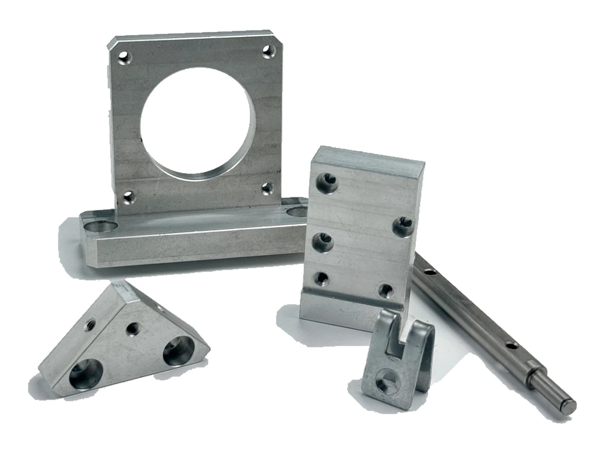
Circular apertures, slots and multi-face fixing features.
Locate mounting holes and reference faces against the mating structure.
Locate slots, apertures and mounting faces against the supported component. Include screw-head and tool clearances.
Review accessible internal corners and the material around holes. A visible bracket shape does not establish its load rating.
Review access to the apertures and fastening faces alongside bracket stiffness during workholding. Opposing setups need a datum strategy that preserves the relationship between the supported axis and the mounting plane.
For mounting brackets, specify the alloy, condition and finish on the drawing. Review the finished interfaces, treatment sequence and inspection requirements before selecting this candidate material.
For mounting brackets, specify the alloy, condition and finish on the drawing. Review the finished interfaces, treatment sequence and inspection requirements before selecting this candidate material.
For mounting brackets, specify the alloy, condition and finish on the drawing. Review the finished interfaces, treatment sequence and inspection requirements before selecting this candidate material.
For mounting brackets, specify the alloy, condition and finish on the drawing. Review the finished interfaces, treatment sequence and inspection requirements before selecting this candidate material.
These grades are engineering selection candidates, not a statement of stock availability or verified capability for every material condition. Material, heat treatment and inspection requirements are subject to factory confirmation against the drawing.
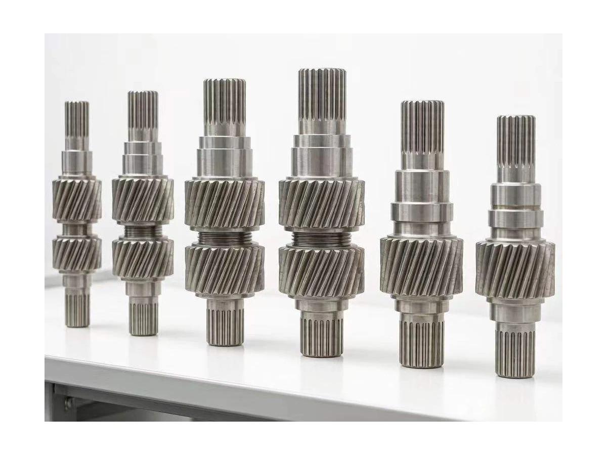
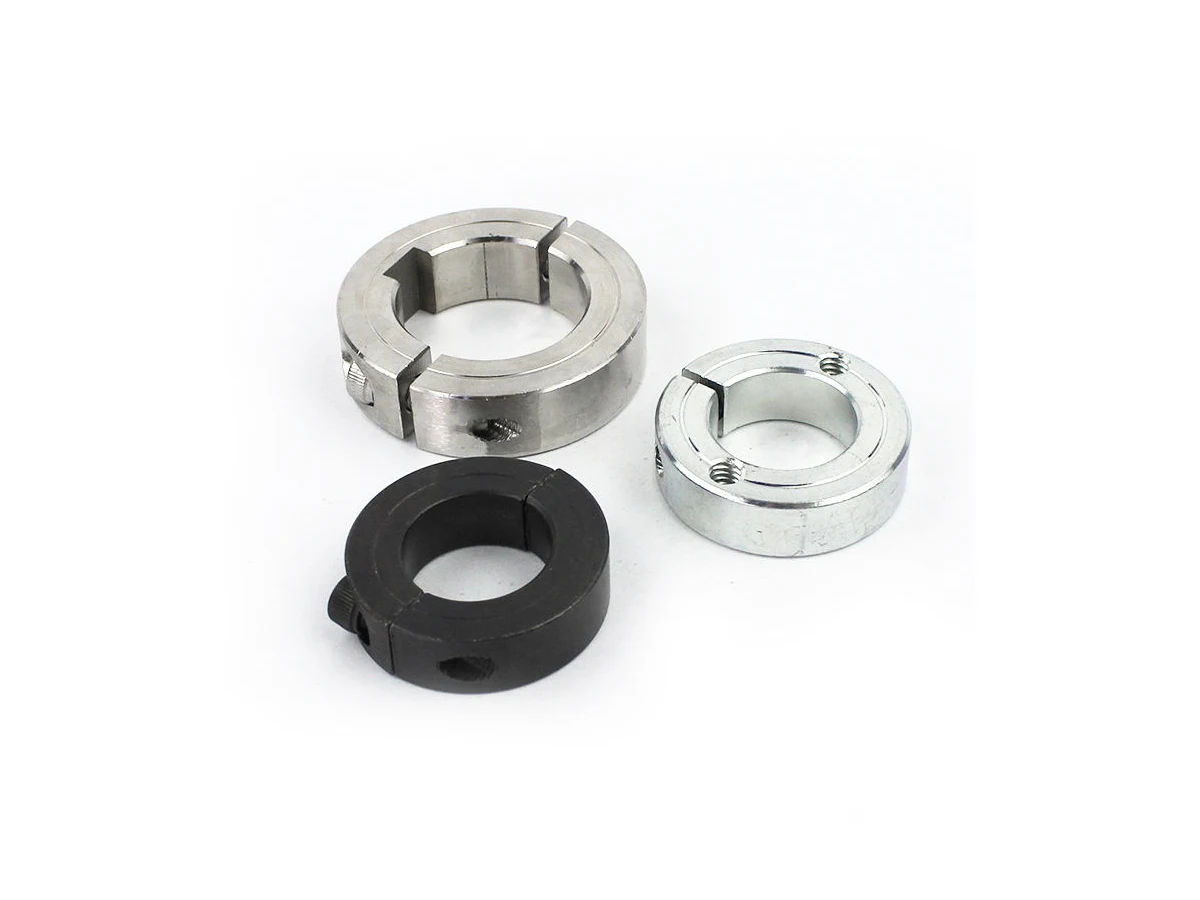
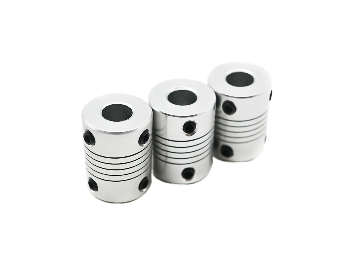
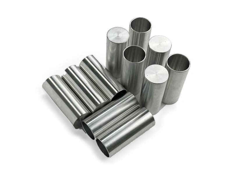
Explore CNC Metals & MaterialsUse the dimensioned drawing to define these requirements. Photographs illustrate visible geometry; they do not establish a standard size, material grade or performance rating.
A bracket may relate a motor interface to a machine base. Review shaft position, bolt access and the supported assembly rather than assuming a universal motor pattern.
Mounting faces and apertures can locate equipment subassemblies. State which surfaces control alignment and which are clearance-only.
Slots may allow assembly adjustment before fastening. Define the allowed travel and final seating condition for inspection and installation.
Relate the supported aperture axis to the mounting plane using functional datums.
Review tool access around slots, deep bores and faces close to supporting walls.
Specify edge treatment and finish on seating surfaces and hardware interfaces.
Agree dimensional acceptance separately from any structural or load validation.
Send the CAD model and project requirements for manufacturing review.
Upload CAD Drawings for a Quote