Machined Geometry
Open cavities, machined faces and mounting holes.
Machined housings and frames with open cavities, access openings and mounting faces. Define the internal envelope and mating structure together so enclosure fit can be reviewed from the drawing.
Upload CAD Drawings for a Quote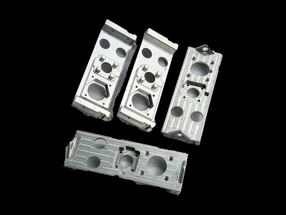
Open cavities, machined faces and mounting holes.
Define pocket clearances and the relationship between mounting faces.
Show cavity depths, wall sections and the working faces of the housing. Distinguish clearance surfaces from controlled interfaces.
Identify features that need access from several faces. Review thin walls and interrupted edges before committing to a machining sequence.
Review pocket milling, bore access and machining on opposing faces as one setup plan. Wall support, internal radii and the location of mounting datums affect how the housing can be held and inspected.
For machined housings & frames, specify the alloy, condition and finish on the drawing. Review the finished interfaces, treatment sequence and inspection requirements before selecting this candidate material.
For machined housings & frames, specify the alloy, condition and finish on the drawing. Review the finished interfaces, treatment sequence and inspection requirements before selecting this candidate material.
For machined housings & frames, specify the alloy, condition and finish on the drawing. Review the finished interfaces, treatment sequence and inspection requirements before selecting this candidate material.
For machined housings & frames, specify the alloy, condition and finish on the drawing. Review the finished interfaces, treatment sequence and inspection requirements before selecting this candidate material.
These grades are engineering selection candidates, not a statement of stock availability or verified capability for every material condition. Material, heat treatment and inspection requirements are subject to factory confirmation against the drawing.
Explore CNC Metals & MaterialsUse the dimensioned drawing to define these requirements. Photographs illustrate visible geometry; they do not establish a standard size, material grade or performance rating.
Internal cavities can accommodate mechanical components while external faces provide mounting references. Review access and installation clearance with the mating equipment.
Frame geometry can position several components around a shared opening. Define the relationships between mounting faces rather than dimensioning each side independently.
Housing prototypes support clearance and fit evaluation. Provide the mating parts and the revision being assessed so dimensional checks match the intended assembly.
Select the assembly mounting faces as datums and review how they remain accessible during machining.
Check cutter entry, pocket depth and corner relief around deep or narrow cavities.
Identify surfaces that need masking or dimensional allowance during finishing.
Agree inspection of the specified hole pattern, bores and mating faces; enclosure appearance does not establish sealing performance.
Send the CAD model and project requirements for manufacturing review.
Upload CAD Drawings for a Quote