Machined Geometry
Stepped bores, counterbores and edge-mounted features.
Bored mounting plates with stepped holes, counterbores and edge features. Coordinate the hole pattern, seating surfaces and fixing access with the components being installed.
Upload CAD Drawings for a Quote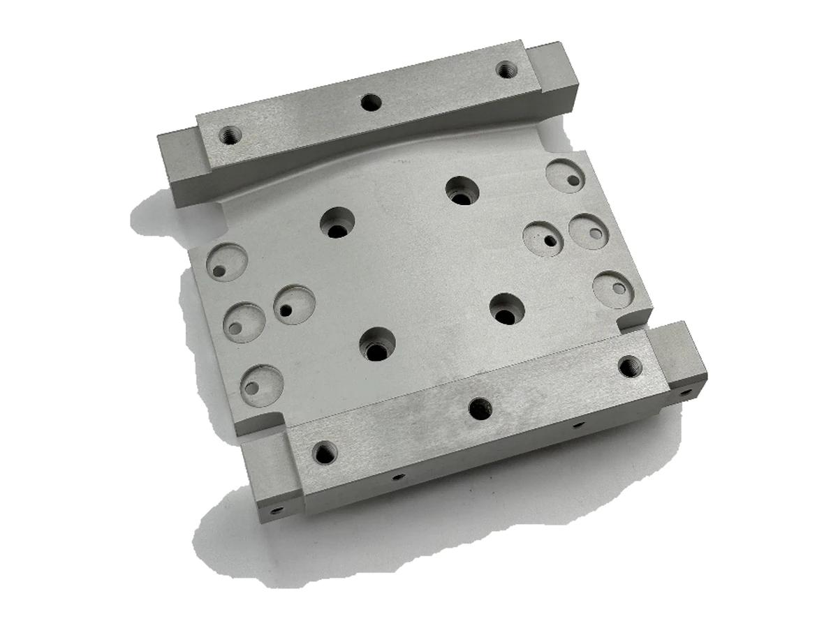
Stepped bores, counterbores and edge-mounted features.
Specify hole patterns, seating faces and assembly access.
Differentiate locating bores, fixing holes and clearance counterbores. Include the mating-component requirements.
Review bore depth, edge access and support during machining. Flatness acceptance must be specified on the drawing.
Review face milling and bore machining around a common datum system. Workholding and machining order should account for the plate section and the final relationship of the stepped bores to the mounting faces.
For bored mounting plate, specify the alloy, condition and finish on the drawing. Review the finished interfaces, treatment sequence and inspection requirements before selecting this candidate material.
For bored mounting plate, specify the alloy, condition and finish on the drawing. Review the finished interfaces, treatment sequence and inspection requirements before selecting this candidate material.
For bored mounting plate, specify the alloy, condition and finish on the drawing. Review the finished interfaces, treatment sequence and inspection requirements before selecting this candidate material.
For bored mounting plate, specify the alloy, condition and finish on the drawing. Review the finished interfaces, treatment sequence and inspection requirements before selecting this candidate material.
These grades are engineering selection candidates, not a statement of stock availability or verified capability for every material condition. Material, heat treatment and inspection requirements are subject to factory confirmation against the drawing.
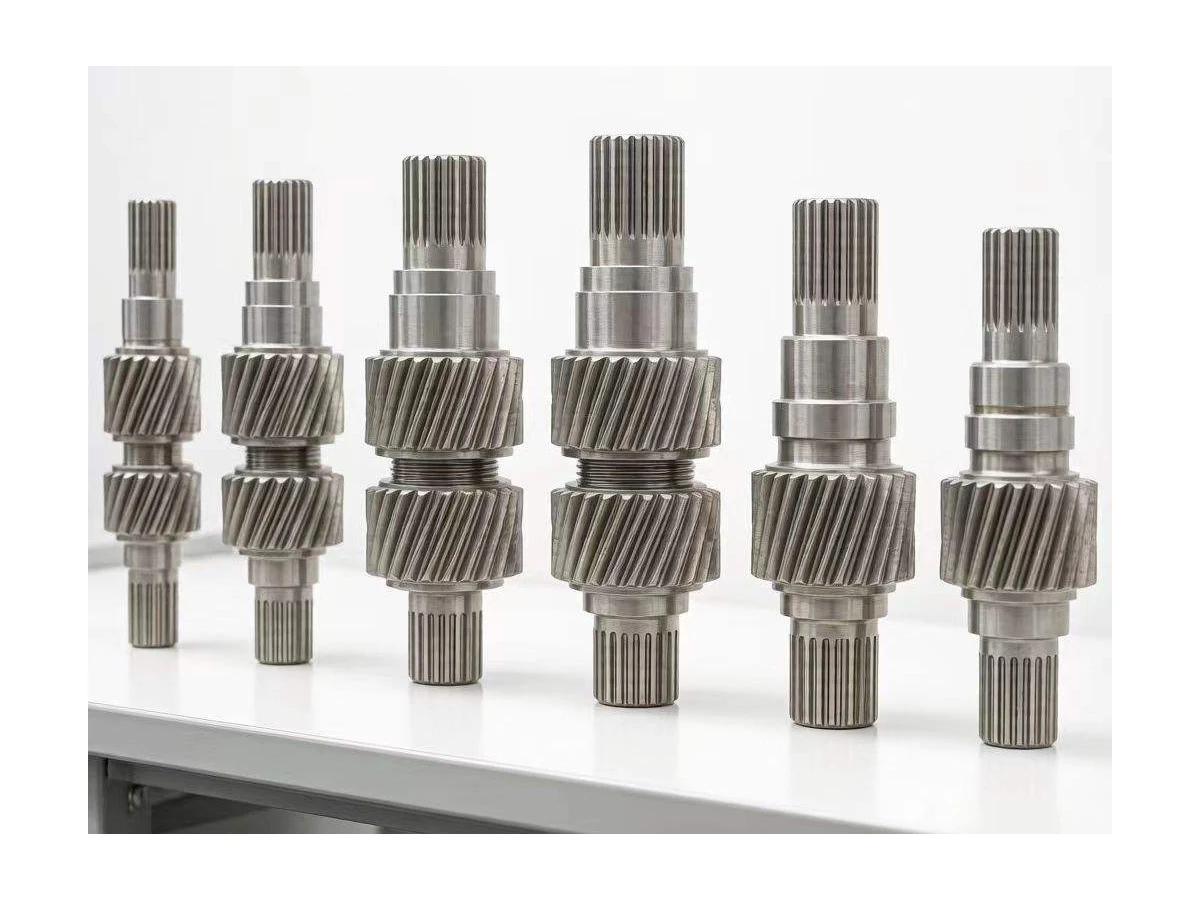
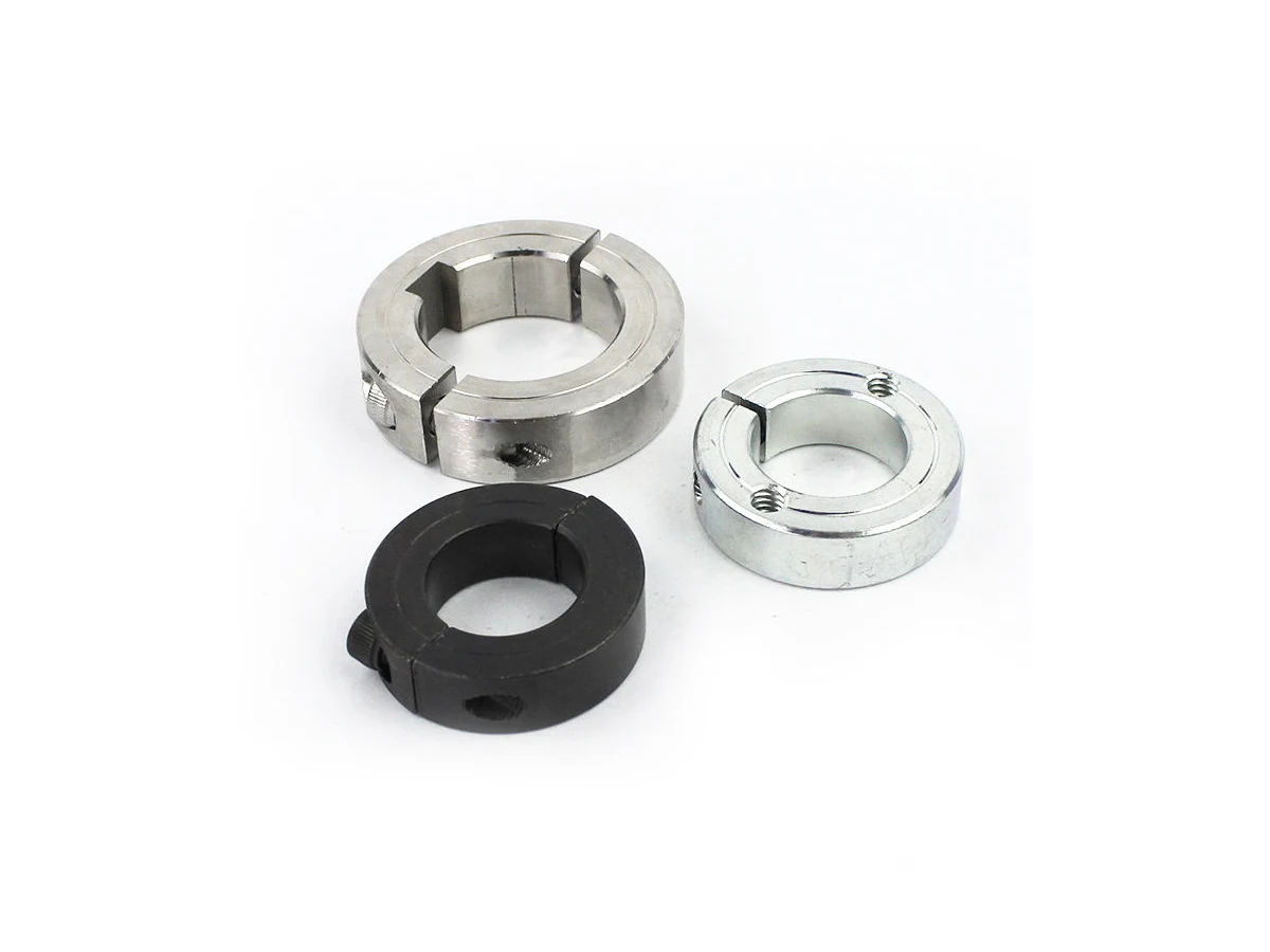
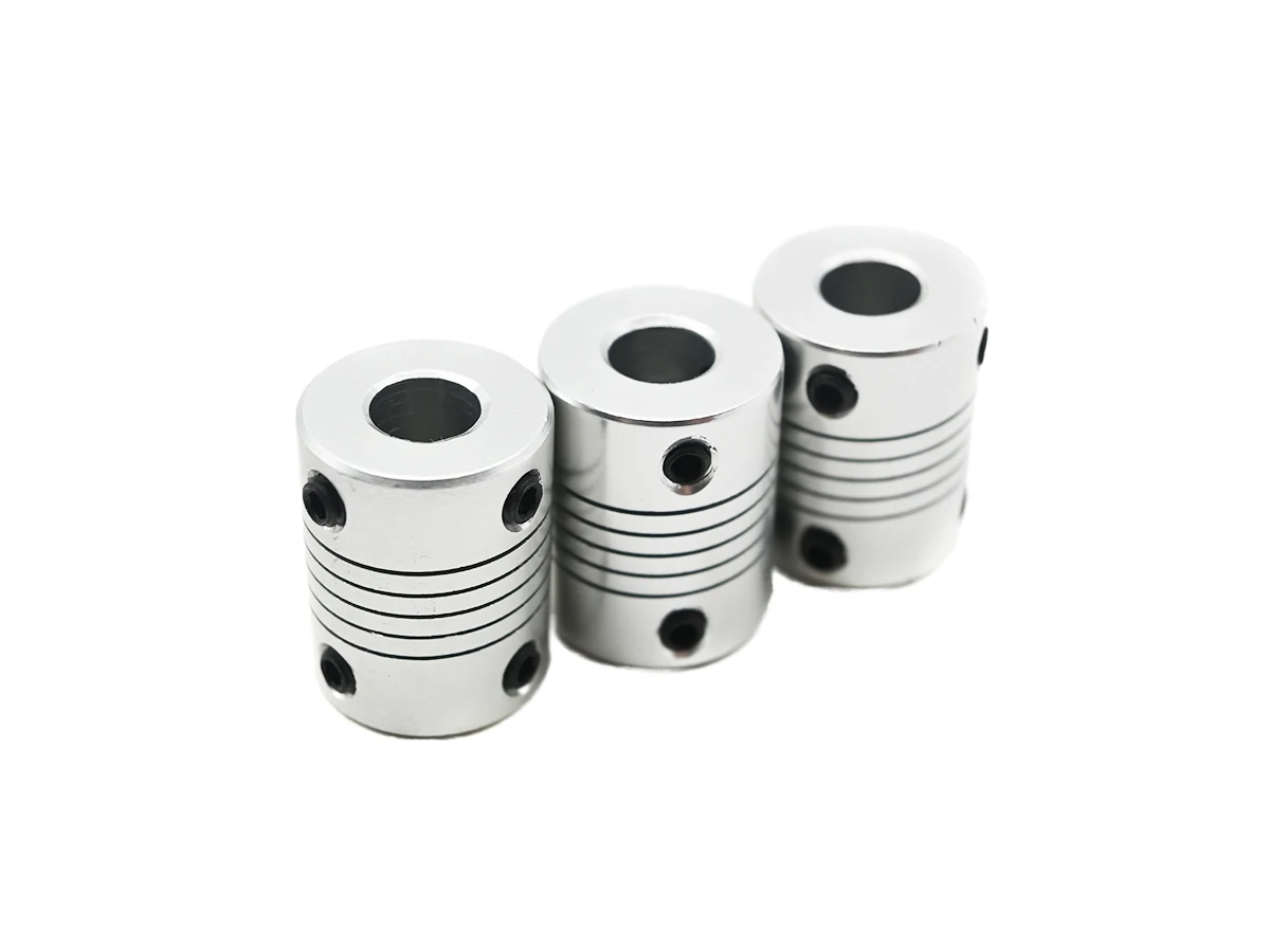
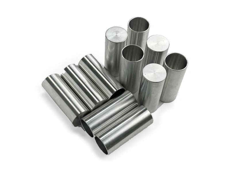
Explore CNC Metals & MaterialsUse the dimensioned drawing to define these requirements. Photographs illustrate visible geometry; they do not establish a standard size, material grade or performance rating.
A plate can connect several mounted components to a base. Relate the locating pattern to the assembled equipment references.
Different hole patterns may join otherwise separate mounting systems. Check overlap, screw access and remaining material before manufacture.
Bores and seating faces can establish repeatable setup locations. Define the locating elements and acceptance method independently of the photograph.
Choose datums that reflect how the plate is seated and located in use.
Allow tool entry and relief for stepped bores and features near plate edges.
Review coating or treatment allowances on controlled holes and seating faces.
Specify the hole-location and surface checks required in the finished state.
Send the CAD model and project requirements for manufacturing review.
Upload CAD Drawings for a Quote