Machined Geometry
Turned profiles, threads and shaped ends.
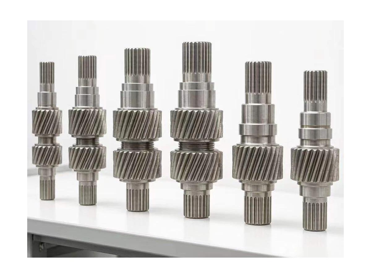
Threaded and stepped pins with turned profiles, shaped interfaces and shoulder seating features. Define the locating function and threaded retention separately on the drawing.
Upload CAD Drawings for a Quote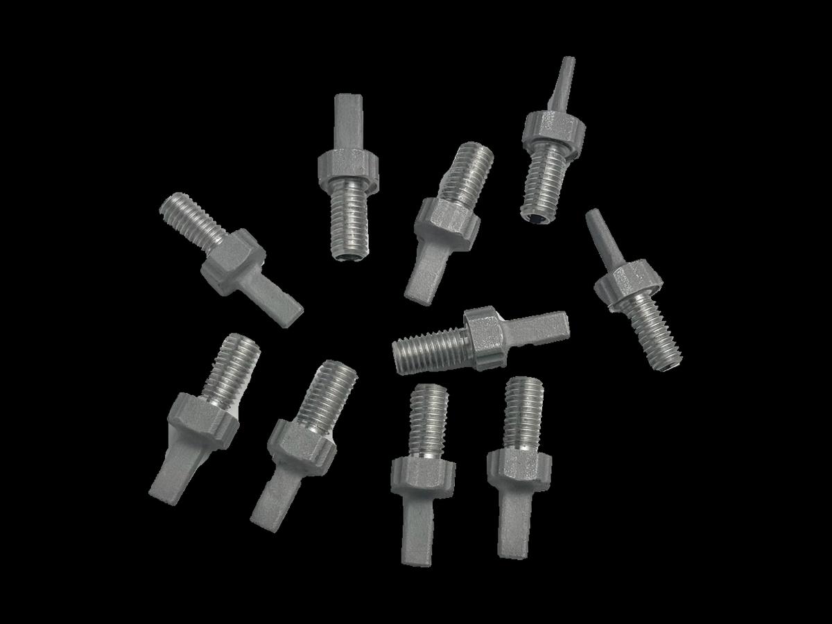
Turned profiles, threads and shaped ends.
Define mating threads, shoulder seating and insertion length.
Identify which diameter locates the assembly and which features provide retention or tool engagement.
Dimension thread runouts and shoulder reliefs so the mating component can seat fully.
Review the turned diameters, thread production and any secondary shaped ends as a sequence. Small sections need support during machining and a clear finished inspection condition.
For threaded & stepped pins, specify the alloy, condition and finish on the drawing. Review the finished interfaces, treatment sequence and inspection requirements before selecting this candidate material.
For threaded & stepped pins, specify the alloy, condition and finish on the drawing. Review the finished interfaces, treatment sequence and inspection requirements before selecting this candidate material.
For threaded & stepped pins, specify the alloy, condition and finish on the drawing. Review the finished interfaces, treatment sequence and inspection requirements before selecting this candidate material.
For threaded & stepped pins, specify the alloy, condition and finish on the drawing. Review the finished interfaces, treatment sequence and inspection requirements before selecting this candidate material.
These grades are engineering selection candidates, not a statement of stock availability or verified capability for every material condition. Material, heat treatment and inspection requirements are subject to factory confirmation against the drawing.
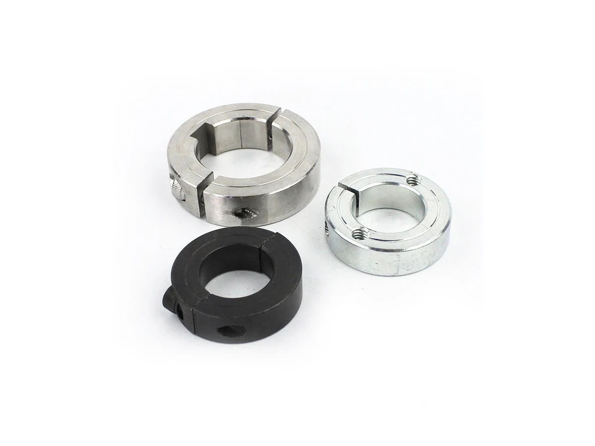
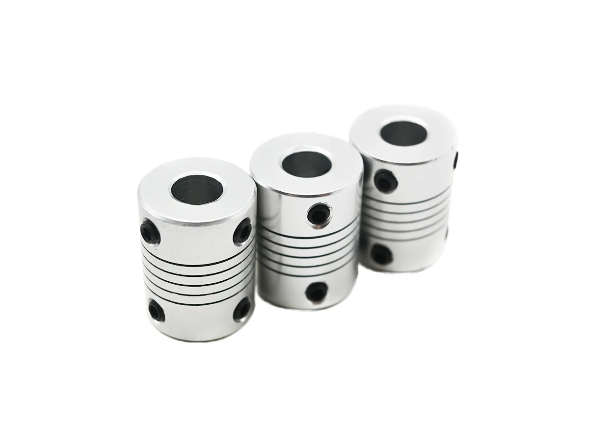
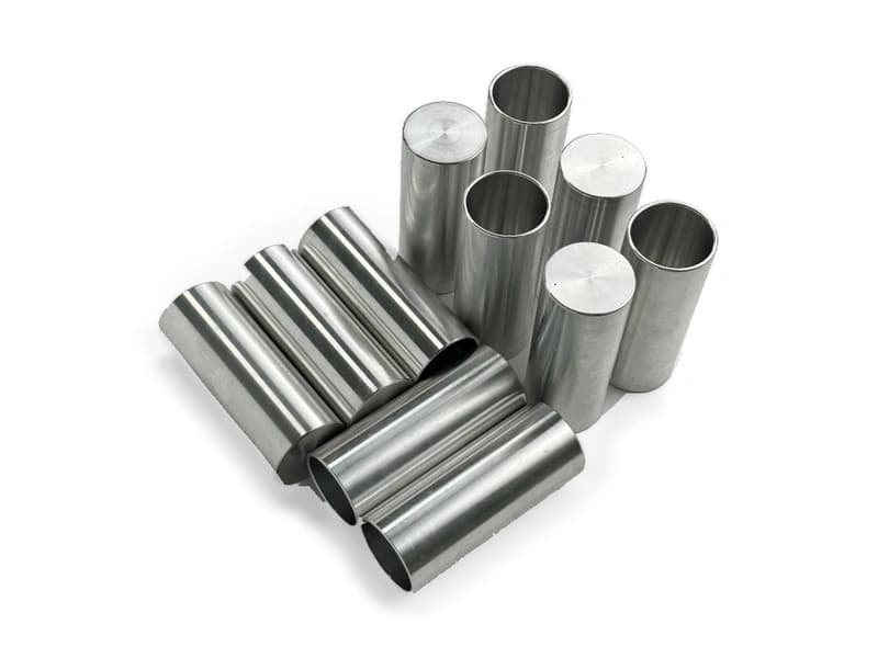
Explore CNC Metals & MaterialsUse the dimensioned drawing to define these requirements. Photographs illustrate visible geometry; they do not establish a standard size, material grade or performance rating.
A pin can locate one component relative to another. Define the fit and insertion condition rather than relying on nominal diameter alone.
A threaded end can provide retention alongside a separate locating section. Check shoulder seating, screw engagement and assembly access.
Drawing-defined pins may position workpieces or fixture elements. State the mating bore and any replacement or adjustment requirements.
Choose the locating diameter and seating shoulder as the functional references.
Check access to thread runouts, flats and closely spaced shoulders.
Define treatment and deburring without damaging locating surfaces or thread entries.
Agree checks for locating fit and threads in their required finished condition.
Send the CAD model and project requirements for manufacturing review.
Upload CAD Drawings for a Quote