Machined Geometry
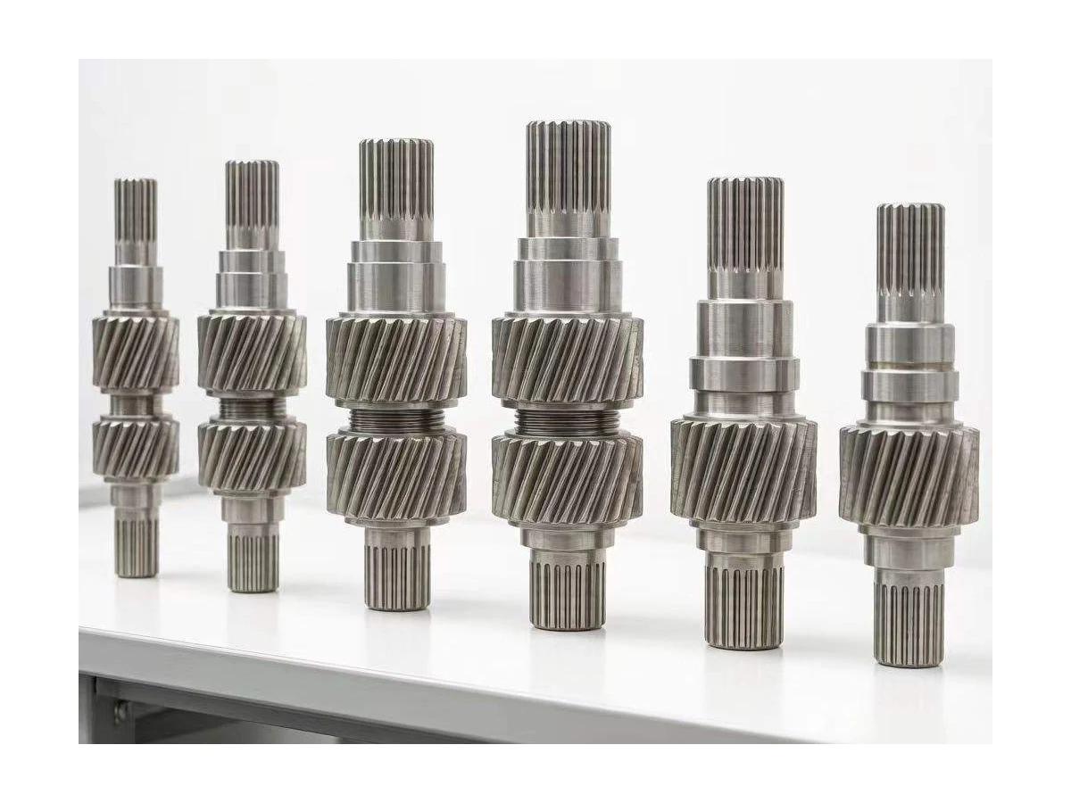
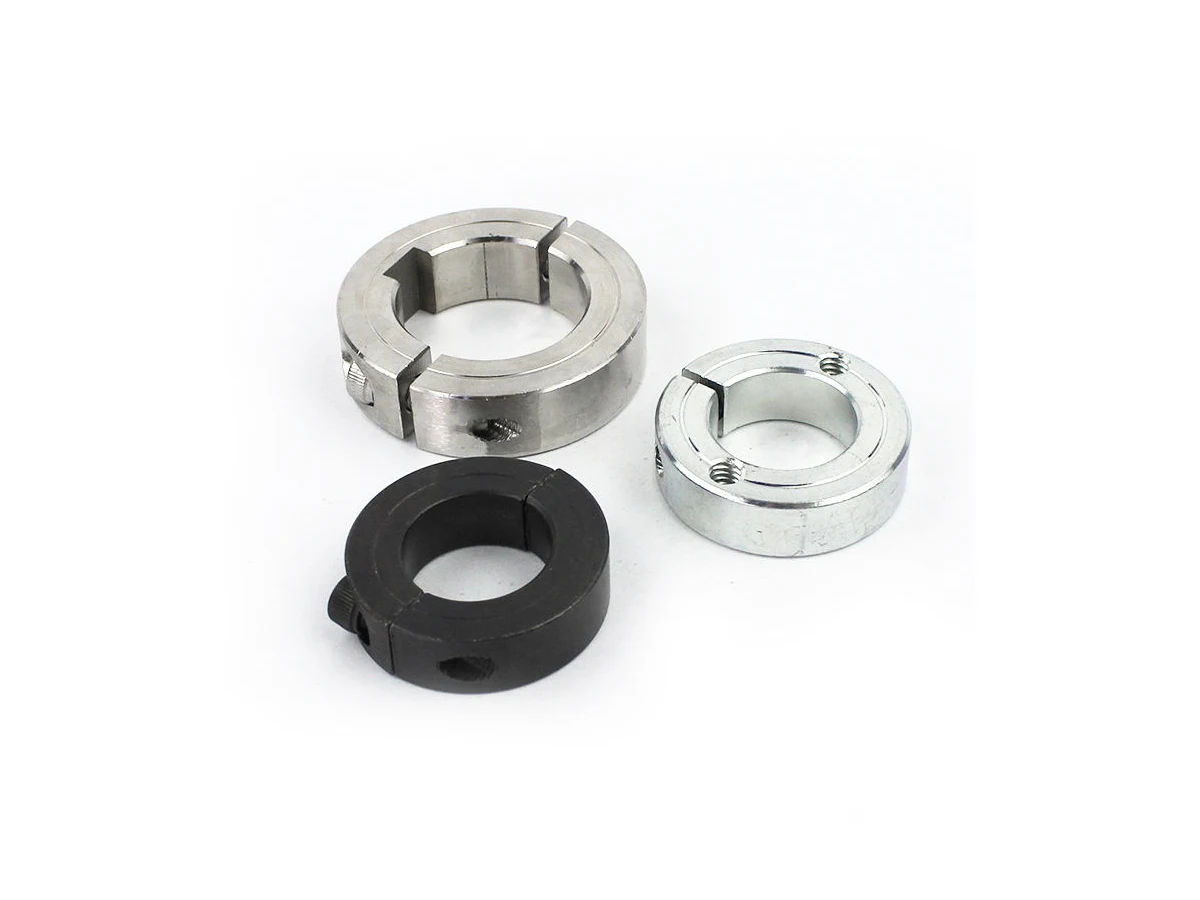
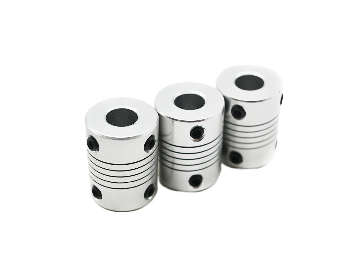
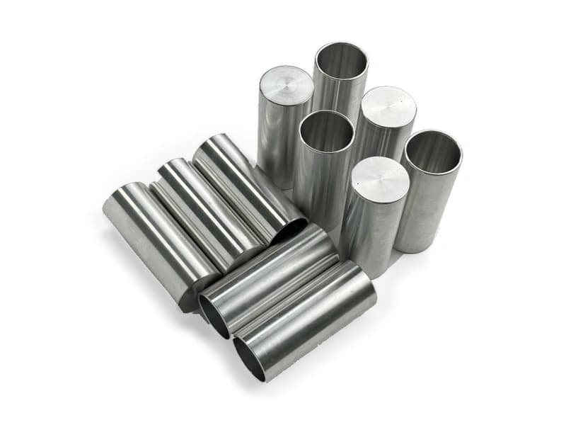
Fine external knurling and flat end faces.
Small cylindrical components with external knurling and flat end faces. Specify the knurled surface and its intended contact or handling function rather than inferring a thread or insert design.
Upload CAD Drawings for a Quote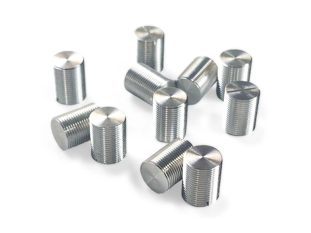
Fine external knurling and flat end faces.
Define contact diameter and the function of the knurled surface.
Define knurl type, coverage and the required finished envelope. Distinguish a grip surface from a controlled locating diameter.
Include any bore or retention feature only when it is defined by the drawing; the exterior photograph does not establish hidden geometry.
Review the knurl specification alongside the turned profile and remaining wall section. The proposed forming or cutting method and the finished outside condition need drawing-specific confirmation.
For knurled cylindrical components, specify the alloy, condition and finish on the drawing. Review the finished interfaces, treatment sequence and inspection requirements before selecting this candidate material.
For knurled cylindrical components, specify the alloy, condition and finish on the drawing. Review the finished interfaces, treatment sequence and inspection requirements before selecting this candidate material.
For knurled cylindrical components, specify the alloy, condition and finish on the drawing. Review the finished interfaces, treatment sequence and inspection requirements before selecting this candidate material.
For knurled cylindrical components, specify the alloy, condition and finish on the drawing. Review the finished interfaces, treatment sequence and inspection requirements before selecting this candidate material.
These grades are engineering selection candidates, not a statement of stock availability or verified capability for every material condition. Material, heat treatment and inspection requirements are subject to factory confirmation against the drawing.
Explore CNC Metals & MaterialsUse the dimensioned drawing to define these requirements. Photographs illustrate visible geometry; they do not establish a standard size, material grade or performance rating.
A knurled surface may provide a manual contact area. Define the required pattern and edge condition for the actual use.
Knurled geometry can interact with a mating assembly in a drawing-defined way. Do not assume a press-fit or retention capacity from appearance alone.
Compact cylindrical parts may combine a textured exterior with other turned features. Provide the complete drawing to separate visible and hidden interfaces.
Separate the knurled exterior from any locating or seating datums.
Review access and part support for the chosen knurl process and short component length.
Specify edge treatment and the acceptable finished pattern condition.
Agree how the knurl envelope and any hidden bores will be measured.
Send the CAD model and project requirements for manufacturing review.
Upload CAD Drawings for a Quote