Machined Geometry
Bored ends, short turned sections and mounting flanges.
Small flanged mechanical connectors with bored ends, turned sections and mounting holes. Define the mating mechanical interfaces without assuming fluid, electrical or sealed service.
Upload CAD Drawings for a Quote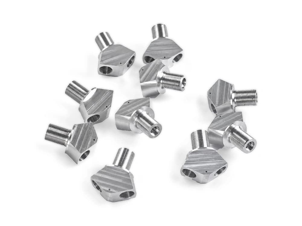
Bored ends, short turned sections and mounting flanges.
Locate fixing holes and bores relative to the mounting face.
Show the working bore and mounting face together with the mating-part envelope.
Dimension the small flange pattern and fastening access. A connector shape alone does not establish pressure or sealing performance.
Review bore access and short turned sections together with flange drilling. Small fixing features and the flange-to-bore relationship should be preserved through the selected workholding sequence.
For small flanged connectors, specify the alloy, condition and finish on the drawing. Review the finished interfaces, treatment sequence and inspection requirements before selecting this candidate material.
For small flanged connectors, specify the alloy, condition and finish on the drawing. Review the finished interfaces, treatment sequence and inspection requirements before selecting this candidate material.
For small flanged connectors, specify the alloy, condition and finish on the drawing. Review the finished interfaces, treatment sequence and inspection requirements before selecting this candidate material.
For small flanged connectors, specify the alloy, condition and finish on the drawing. Review the finished interfaces, treatment sequence and inspection requirements before selecting this candidate material.
These grades are engineering selection candidates, not a statement of stock availability or verified capability for every material condition. Material, heat treatment and inspection requirements are subject to factory confirmation against the drawing.
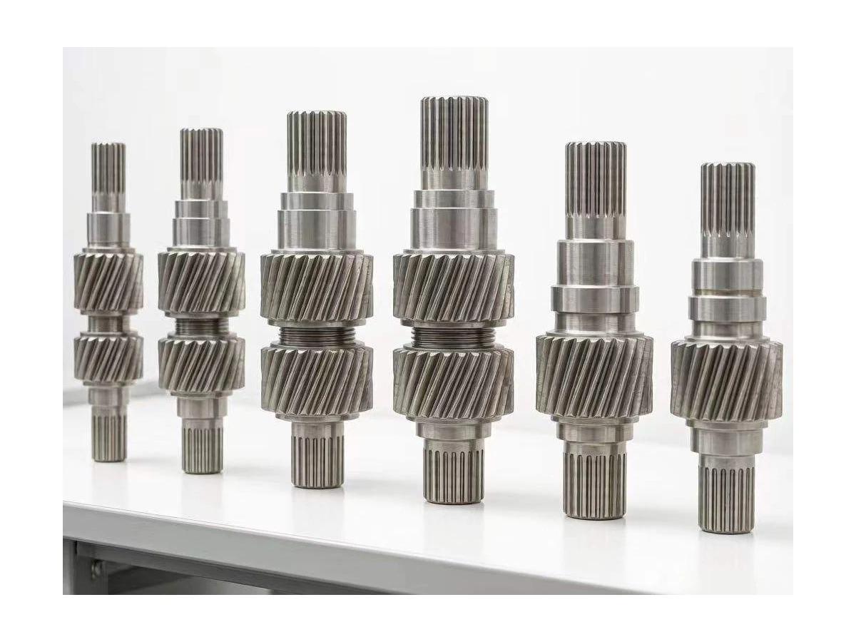
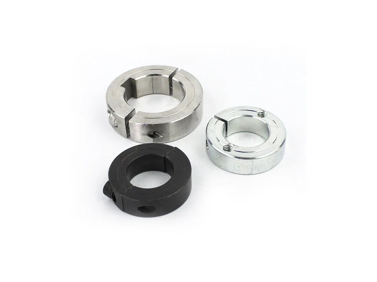
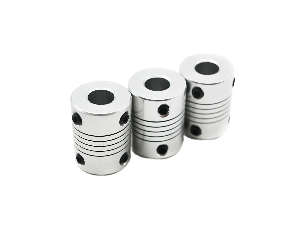
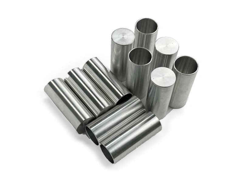
Explore CNC Metals & MaterialsUse the dimensioned drawing to define these requirements. Photographs illustrate visible geometry; they do not establish a standard size, material grade or performance rating.
The flanged geometry can attach a cylindrical interface to another component. Define the bore fit and retention arrangement.
Small flange patterns may be used where installation space is limited. Review fastener access and the mating-face envelope.
Drawing-defined connectors can support assembly fit checks. Any fluid, electrical or sealing requirements need separate specifications and validation.
Relate the bore and flange pattern to the actual working face.
Check access to short bores, small holes and features near the flange edge.
Define burr limits and finished condition at the bore entry and mounting face.
Agree dimensional inspection and separately specify any functional tests required by the design.
Send the CAD model and project requirements for manufacturing review.
Upload CAD Drawings for a Quote